Operating the iVTI
Important
Before operating the iVTI please familiarize yourself with the principle of operations described in the section iVTI Overview.
The following section provides information about day-to-day operation of the cryostat. If you need assistance troubleshooting iVTI operations, please first consult the manual or contact Bridge12 or CRYOGENIC.
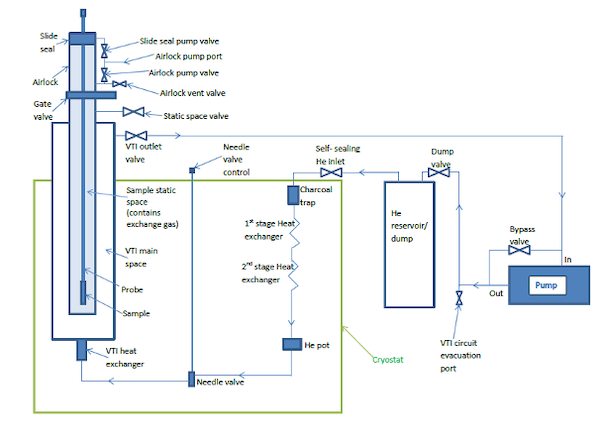
Schematic of the iVTI
The iVTI operates by circulating helium gas in a closed-loop circuit. A schematic of the circuit is shown above. The following instructions assume the magnet is at its base temperature and the iVTI has passed operational checks.
Cooldown of the iVTI
To cooldown the cryostat follow these instructions:
- Make sure the dry pump bypass valve (V16) is closed.
- Make sure the helium reservoir valve (V12) and the iVTI outlet valve (V11) are open.
- Start the dry pump and adjust the needle valve to a pressure of approximately 5-8 mbar at the head of the iVTI. Please note the needle valve may require several further adjustments as the temperature profile within the flow circuit varies whilst steady-state flow conditions are established in the circuit.
While the cryostat cools down, the pressure of the helium reservoir will decrease as more helium condenses in the helium pot.
Setting the Cryostat Temperature and Regulating the Helium Flow
Setting the Temperature
The temperature at the position of the sample is set at the temperature controller. This can be done either manually at the front panel of the temperature controller or through the spectrometer control software SpecMan4EPR. Under normal operations, when there is an EPR probe installed, the temperature of the cryostat is regulated based on the probe temperature sensor readings to give the most accurate control over the temperature at the position of the sample. Once the temperature is set, either on the front panel or through SpecMan4EPR, the user needs to adjust the helium flow by adjusting the needle valve. However, once the desired temperature is reached, no further optimization is required.
Optimization of the temperature controller PID and heater range parameters is beneficial if the ultimate system performance is to be achieved. The parameters may vary depending upon the flow rate established in the circuit. Typical starting values for the PID settings are 250,120,30 which will provide reasonable control over the whole temperature range. However, the user is encouraged to adjust PID settings to further optimize the system as an experience of the iVTI is established. The heat exchanger is fitted with a heater (30 Ohm / 30 W). Under no circumstances should a current greater than 1A be applied to the heat exchanger heater, as it will fuse the leads.
Setting the Needle Valve for Optimum Flow Control
The needle valve creates a controllable impedance for the helium circulation. It is set initially and thereafter should need only occasional adjustment. A dial gauge is fitted at the top of the iVTI to allow the user to set and monitor the flow rate (directly related to pressure). A pressure between 5 and 15 mbar at the top of the iVTI is recommended. The optimum value is specific to each system.
Under normal conditions, a pressure of about 10 mbar can cover a wide range of temperatures. Especially, for experiments that are performed at about 50 to 60 K, the position of the needle valve rarely has to be changed.
To operate at temperatures below 10 K, the pressure may have to be adjusted using the needle valve. In this case, the optimum value will correspond to the vapour pressure curve as shown in the figure below.
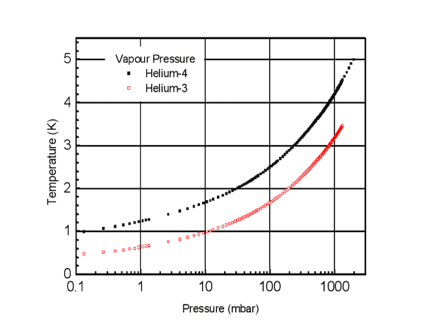
Helium Vapor Pressure
In general, if the helium flow rate is too low there may not be enough cooling power available from the circulating helium and the system may not reach the base temperature of the iVTI. A slightly too high a flow rate and the system will not reach base temperature because it is not following the vapour pressure curve.
However, if the flow rate is far too high the amount of heat that needs to be extracted from the circulating helium will exceed the cooling power of the cryocooler. In this case, the temperature of the cryocooler 2nd stage, magnet and helium pot will increase and the liquefaction of helium in the iVTI circuit will slow or stop. Under these circumstances, the helium pot will eventually empty preventing the iVTI from achieving base temperature. The associated increase in temperature will also affect the magnet ramp rates.
It should be noted that the helium flow is also affected by the impedance of the tubes close to the iVTI heat exchanger. The overall impedance depends on the temperature of the heat exchanger. A higher driving pressure is needed between the helium pot and the iVTI when the iVTI is at a high temperature than when it is at a low temperature. The liquid helium in the helium pot is effectively in equilibrium. So the pressure of the gas above the liquid in the helium pot follows the vapour pressure curve for helium 4 shown in the figure above. Since the inlet circuit has a low impedance, the pressure in the helium reservoir is close to that at the helium pot and can be used as a gauge as to how much helium has been condensed into the pot. A heater on the helium pot is used to control the temperature of the helium pot and hence control the driving pressure. The temperature is set to a recommended value of 3.1 K. The helium pot temperature is controlled via a software PID loop.
Changing the Sample
During the process of changing the sample, the iVTI circuit will continue to run and the dry pump should not be switched off. To change the sample, follow these instructions:
- Removing the Sample
- If you want to insert/replace a new sample, make sure the sample is properly mounted on the sample stick. If you want to remove the sample without inserting a new sample, make sure you have a blind plug handy.
- Make sure the experiment is finished.
- Make sure helium purge gas is available and the pressure regulator is set to the correct value. For the sample exchange circuit, the pressure regulator should be set to a pressure of 3-5 psi.
- Open the valve to the cryostat, located at the top of the magnet and observe the pressure inside the cryostat. You should charge the cryostat space to about 1 psi. A safety valve, located close to the valve will release all excess pressure.
- Loosen the nut securing the sample stick.
- Slowly pull out the sample stick. The sample stick has holes at the top and bottom of the G10 section (green). Once the top hole passes the nut securing the sample stick, cold helium gas will exit the hole. Pull the sample stick out of the probe and properly store the sample. While the purge gas is running, air is prevented to enter the sample space.
- Inserting the Sample
- With the purge gas running, insert the sample stick into the probe.
- Slowly lower the sample stick into the probe. Once the bottom venting holes of the sample stick have past the nut securing the sample stick the helium purge gas will exit at the top holes of the sample stick. Wait for a couple seconds to purge the space inside the of the sample stick.
- Optionally, open the nut at the top of the sample stick to purge the space inside the stainless steel section of the sample stick.
- Slowly push the sample stick into the resonator. At this point, the user should also monitor the resonator tuning in the control software. Once the sample tube is entering the resonator, the frequency will shift to a lower value. Push the sample stick until it is properly seated at the top of the resonator.
- Tighten the nut securing the sample stick. Important, this only needs to be hand-tightened. Do not use any tools to tighten this nut.
- Close the valve to the helium purge gas supply.
- Switch on the diaphragm pump to evacuate the sample space. Lower the pressure to about 200 - 500 mbar. The exact value depends on desired temperature and will require some user experience.
- Close the valve to the iVTI located at the top of the magnet.
- Turn off the diaphragm pump.
Once the sample is loaded into the resonator make sure to close all valves to the helium supply for purging.