Bridge12 X-IF System Overview
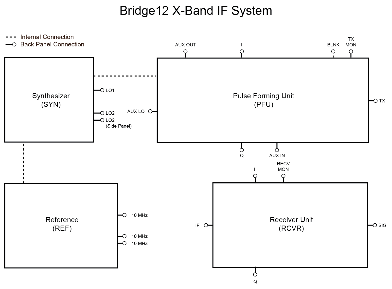
Bridge12 X-IF Overview Schematic
The Bridge12 X-IF system consists of four different sub-systems:
- Synthesizer (SYN): - Two-channel microwave synthesizer.
- Reference Clock (REF): - Internal 10 MHz reference clock.
- Pulse Forming Unit (PFU): - IQ mixer based pulse forming unit.
- Receiver Unit (RCVR): - IQ mixer based receiver unit with video amplifiers.
A schematic of the entire system is shown in the figure above. Most of the connections of the individual sub-systems are routed to the back panel of the system (shown as circles) to provide the user maximum flexibility. Only a few connections are made internally and cannot changed by the user (dashed lines). In the following section a brief description of each sub-systems is given.
Synthesizer (SYN)
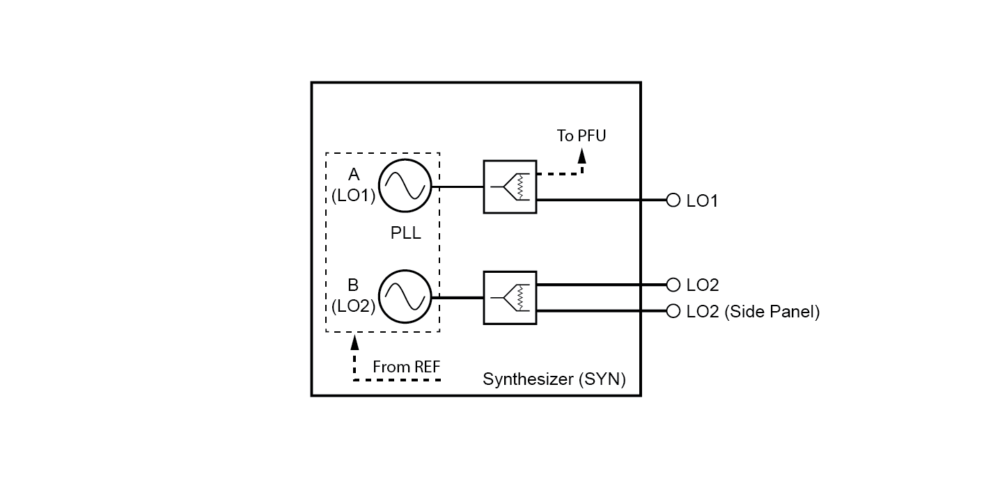
The Bridge12 X-IF system has an integrated microwave synthesizer with two independent channels, LO1 and LO2. The signal of both channels is split into two signal paths. Both signals (LO1 and LO2) are available on the back panel. LO1 is also connected internally to the input of the Pulse Forming Unit (PFU). LO2 is also available on the side panel of the X-IF system, below the signal (SIG) input.
Both microwave synthesizers are locked to the internal 10 MHz reference clock. By default both channels are phase locked to each other. This can be changed through the software.
Reference (REF)
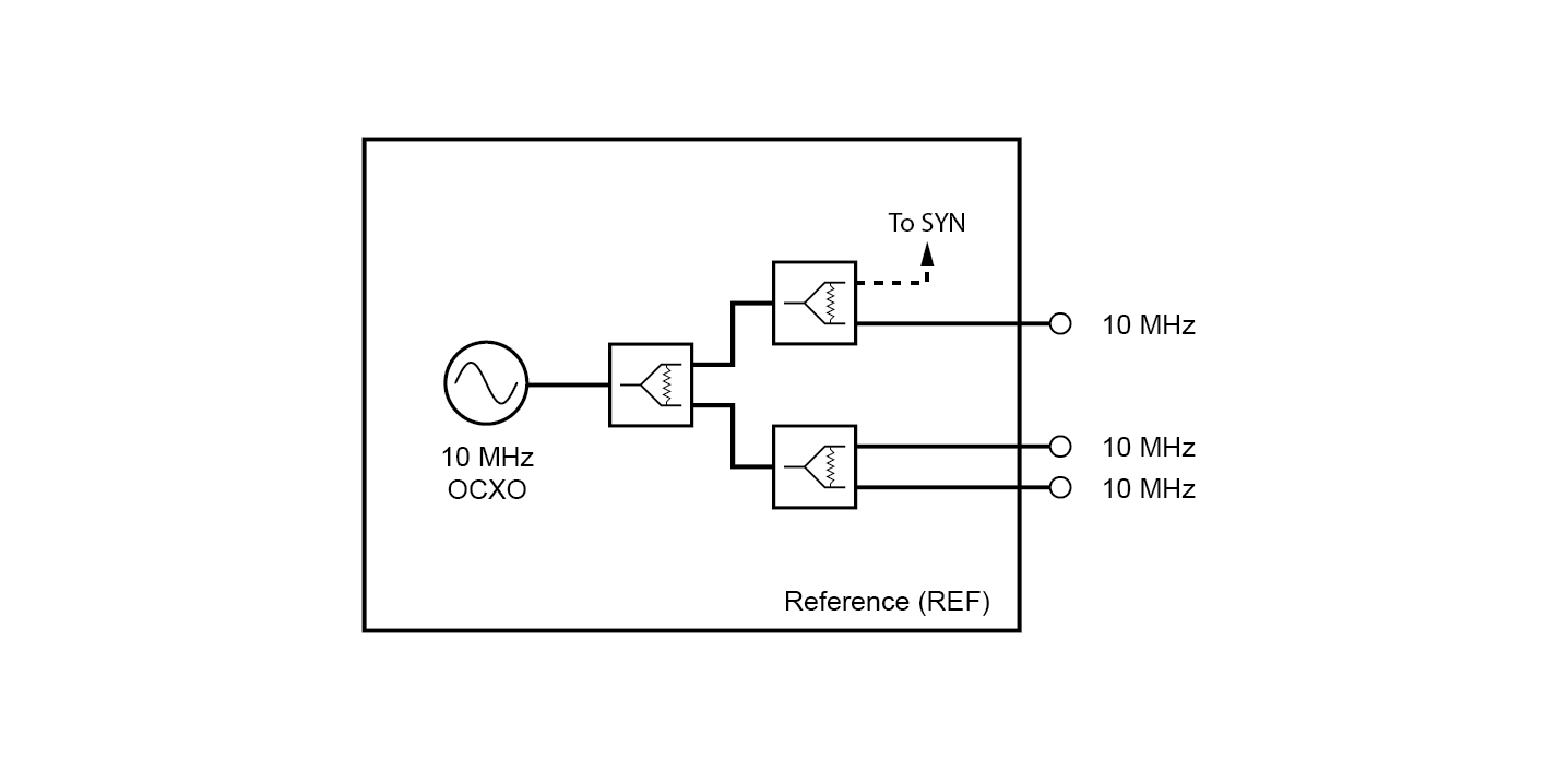
The Bridge12 X-IF system has an integrated oven-stabilized 10 MHz reference clock. Three 10 MHz outputs of the reference clock are available on the backpanel. This can be used to sync other devices such as an AWG or Digitizer. One channel of the clock is internally connected to the synthesizer for phase locking.
Note
The output level of all 10 MHz reference back panel connectors is 2 Vpp into 50 Ω.
Pulse Forming Unit (PFU)
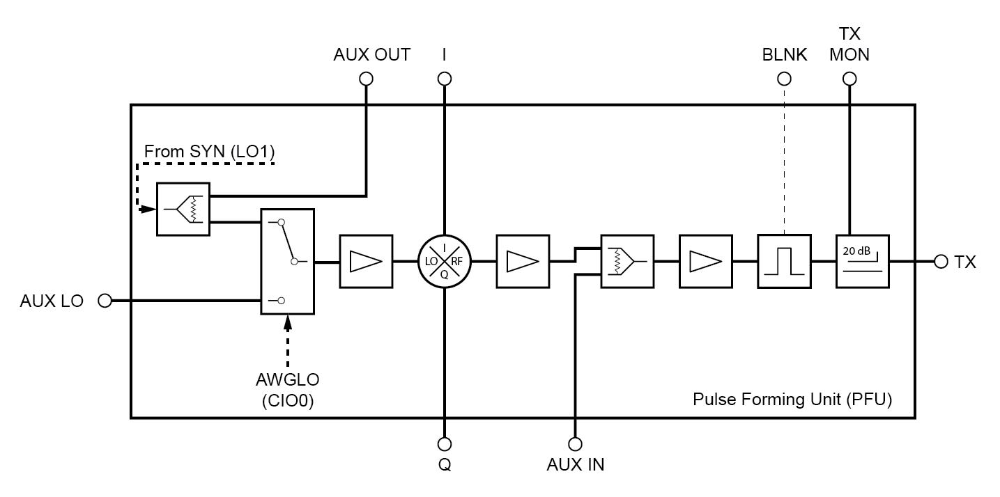
Pulses in the X-IF system are created by the Pulse Forming Unit (PFU). At the heart of the PFU is an I/Q mixer. Both channels, I and Q would normally be driven by an AWG. However, to create rectangular pulses at the LO1 frequency, these channels can also be driven by rectangular pulses created by a pulse programmer.
Internally, the LO of the IQ mixer is connected to LO1 of the synthesizer. However, a different LO signal can be supplied through the back panel connector AUX LO. If a rectangular pulse is applied to the I and Q channels, the pulse frequency will be identical to LO1. If a waveform is supplied (e.g. rectangular pulse at f(AWG) = 250 MHz) the output frequency at TX will be LO1 + f(AWG).
The output signal of the IQ mixer (RF) is amplified and sent to the TX back panel connector. The PFU has a blanking switch. The BLNK gate should be connected to a pulse programmer (or a marker/channel of the AWG if available). The gate is active HIGH. In between pulses, this gate should be LOW to minimize any LO bleed-through.
The microwave pulses generated by the PFU can be directly monitored on the TX MON backpanel connector.
An auxillary LO signal can be supplied to the IQ mixer by connecting the AUX LO input to for example the LO2or an external synthesizer. The rise/fall time for this switch is about 10 ns. This can be used for example to create a non-coherent microwave pump pulse in a DEER experiment. Alternatively, an additional signal can be supplied to the AUX IN connector.
PFU Control Signals
| Component | SpecMan Control Signal | LabJack Control Signal | Function |
|---|---|---|---|
| AUX LO Switch | AWGLO | CIO0 | Select LO signal for IQ mixer |
Receiver Unit (RCVR)
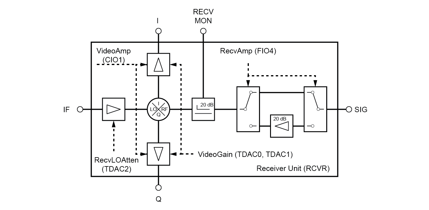
The Bridge12 X-IF is equipped with a IQ mixer based Receiver Unit. The signal from the probe is connected to the SIG side panel connector.
Note
To give the user the most flexibility what type of probe to connect to the system, the X-IF system does not have an integrated low-noise amplifier (LNA) or circulator. For X-Band operation an external circulator/LNA module is available that can be connected to the X-IF system. Otherwise, the circulator and LNA is part of the frequency extension.
The input signal can be further amplified using an internal amplifier with about 20 dB gain. The receive signal can be monitored on the RECV MON back panel connector. This signal is sent to the RF port of the IQ mixer. The LO signal for the IQ mixer is supplied to the IF back panel connector. For X-Band operation, IF is typically connected to LO1, the same signal supplied to the PFU.
Note
If the IF port is connected to the LO1 port and an AWG is used to generated pulses at an offset frequency of f(AWG), the detected EPR signal is at this frequency. The signal can then be digitally demodulated and filtered.
The down-converted signal is further amplified by a pair of video amplifiers. The gain of the video amplifiers is variable, and the video amplifiers can also be bypassed. The down-converted EPR signal is available at the I and Q back panel connectors. This signal can be either sent to a digitizer or lock-in amplifier for detection.
RCVR Control Signals
These signals
| Component | SpecMan Control Signal | LabJack Control Signal | Function |
|---|---|---|---|
| Microwave Amplifier | RecvAmp | FIO4 | Pull High to enable the microwave signal amplifier |
| Video Amplifiers | VideoAmp | CIO1 | Pull HIGH to enable the video amplifiers |
| Video Amplifier Gain | VideoGain | TDAC0, TDAC1 | Variable gain control of the video amplifiers |
| LO Amplifier | RecvLOAtten | TDAC2 | Receiver LO amplifier to set LO level of IQ mixer |