Theory of Operation
The PTR was first described in the literature by Howard et al. operating at a frequency of 28 GHz. Despite its low insertion loss, the PTR has only been used in QO systens for high-field EPR/DNP spectroscopy in some rare instances.
Theory
Wire Grids
Before discussing the PTR in more detail, we will briefly review some fundamental properties of wire grid polarizers.
Free-standing wire grid polarizers made from cylindrical metallic wires either transmit or reflect electromagnetic radiation depending on the orientation (polarization) of the incident E field vector with respect to the grid wire orientation. For cylindrical wires with wire radius \(d\) and wire separation distance \(S\) with \(d \ll S\), the frequency dependent transmission coefficient for an electric field vector oriented parallel to the wire grid can be calculated using the Jones Matrix formalism. The corresponding reflection and transmission matrices are:
$$ C_{R} = \begin{pmatrix} -\cos^{2}{\theta} & -\cos{\theta} \sin{\theta} \\ \cos{\theta} \sin{\theta} & \sin^{2}{\theta} \end{pmatrix} $$
and
$$ C_{T} = \begin{pmatrix} \sin^{2}{\theta} & -\cos{\theta} \sin{\theta} \\ -\cos{\theta} \sin{\theta} & \cos^{2}{\theta} \end{pmatrix}. $$
This only correct if the grid orientation to be perpendicular to the propagation direction of the beam (\(\theta^{ \prime} = 0^{\circ}\)). However, if the purpose of the grid is to clean up the polarization of the microwave beam, the resulting reflected microwave power should be directed away form the source and not directly reflected back. This can be achieved by orienting the grid at an angle of \(\theta^{\prime} = 45^{\circ}\). In this case determining the reflection and transmission coefficients is less intuitive. This is summarized in the following figure (Figure 1).
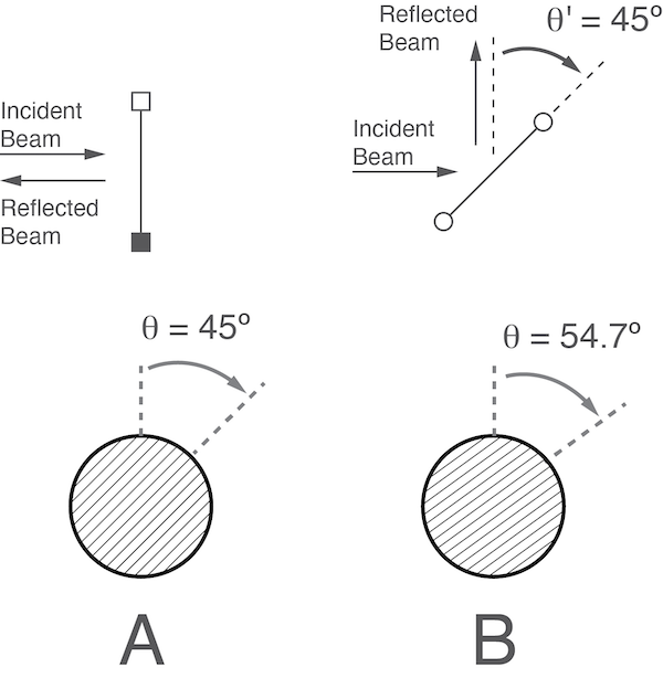
Figure 1: Grid orientation for partial beam reflection/transmission
If the grid is oriented perpendicular to the beam propagation direction (\(\theta^{ \prime} = 0^{\circ}\)) the free-standing wire grid needs to be rotated by (\(\theta = 45^{\circ}\)) to transmit 50 % of the power (see Figure 1A). On the other hand, if the grid is oriented at an angle (\(\theta^{ \prime} = 45^{\circ}\)) the wire grid needs to be rotated by (\(\theta = 54.7^{\circ}\)) to transmit 50 % of the power and reflect 50 % of the power (see Figure 1B). For more details check out Paul Goldsmith’s book Quasioptical Systems: Gaussian Beam Quasioptical Propagation and Applications (chapter 8.6.2, page 210).
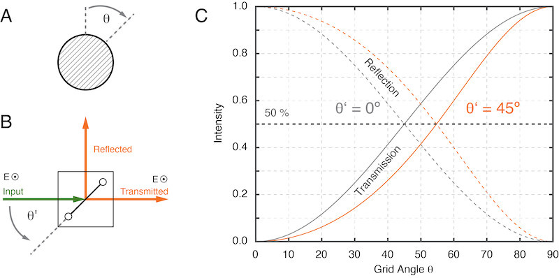
Figure 2: The free-standing wire grid as a beam splitter
The power transmission and reflection for a variable grid is shown in Figure 2. By rotating the grid and varying the angle \(\theta\) from 0º to 90º the beam can be continuously attenuated. Depending on the quality of the grid this attenuation can reach values of - 30 dB or lower.
Polarization Transforming Reflector (PTR)
The PTR consists of two principle components: 1) A free-standing wire grid and 2) A flat metal reflector. The free-standing wire grid is made from metallic wires having a diameter of d and separated by a distance of S (see figure below). Directly located behind the grid is a flat mirror. A schematic of the PTR is shown in Figure 2 (left).
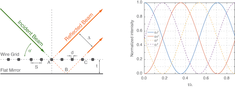
Figure 2: Bridge12 Polarization Transforming Reflector (PTR). Left: Schematic of the PTR. Right: Dependance of the output polarization from the mirror/grid separation distance. Ev - vertically polarized e-field, Eh - horizontally polarized e-field, Er - right hand circularly polarized e-field, El - left hand circularly polarized e-field.
By changing t, the distance between the flat mirror and the wire grid polarizer of the PTR it is possible to change the polarization state of e.g. a linearly polarized Gaussian incident beam to from linear to circular clockwise and counter-clockwise polarization (Figure 2, right).
How it works
Assuming the gird/mirror pair of the PTR is oriented at angle \(\theta = 45^{\circ}\) with respect to the propagation direction of the incident beam and a grid wire orientation of (\(\theta^{ \prime} = 54.7^{\circ}\)) half of the power of the incident beam will be reflected by the wire grid at point A (see Figure 2, left). The remaining portion of the beam will travel through the grid and be reflected by the flat mirror surface at point B (see Figure 2, left).
Depending upon the distance t between the wire grid and the flat mirror surface, the portion of the beam transmitted by the wire grid will have to travel an additional distance ABC (see Figure 2, left) and will accumulate a phase difference \(\rho\) with respect to the portion of the beam taht is reflected by the wire grid at point A (see Figure 2, left).
For the incoming beam, having a wavelength of \(\lambda \), propagating at an incident angle \(\theta = 45^{\circ}\) and a grid–mirror separation of t, the optical path difference P to travel the additional distance is:
$$ P = AB + BC \\ P = 2t \cos(\theta^{\prime}). $$
The phase difference \(\rho\) between orthogonal components is given by
$$ \rho = 4 \pi t \cos(\theta^{\prime} \lambda), $$
and the separation distance between orthogonal components \(\Delta\) (beam walk-off, Figure 2 right) is given by
$$ \Delta = 2t \sin(\theta^{\prime}). $$
By changing the distance t, it is possible to change the phase difference between the two beam components and therefore to change the polarization of the e-field of the reflected beam, e.g., from linear to circular or arbitrary linear polarization orthogonal to the propagation axis, with respect to the reflected beam. Choosing the correct distance t, an incident linearly polarized THz beam can therefore be transformed into a beam with a phase difference given by \(\rho\) with respect to the orthogonal polarization. This property enables transformation of, e.g., linear polarization to circular polarization, similar to a quarter-lambda waveplate.