Digital Demodulation
The Bridge12 X-Band IF system supports digital demodulation. Digital demodulation allows for easy removal of baseline artifacts and will result in a much cleaner signal detection. Instead of down-converting the EPR signal to DC level, the LO frequency is slightly offset and the signal is detected at a frequency of e.g. 200 MHz. The exact frequency depends on the sampling rate and input bandwidth of the digitizer (or oscilloscope).
Information
Digital demodulation is highly recommended for the X-Band IF system. Even an offset of just 20 MHz will greatly remove many artifacts from the baseline.
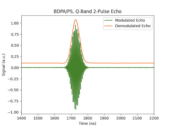
The example below shows a digitally demodulated signal of a 2-pulse Hahn echo of a sample of BDPA in polystyrene, recorded at Q-band frequencies.
We recommend using an intermediate frequency of about half the bandwidth of the digitizer. For example, if the digitizer has an input bandwidth of 400 MHz, we recommend to choose an intermediate frequency of 200 MHz.
Digital Demodulation (Recommended Operation)
To acquire the EPR signal at a This offset can be achieved in two ways:
1. Offsetting the AWG Frequency
The simplest way to use digital demodulation is by offsetting the frequency for the AWG generated microwave pulses. Instead of generating a rectangular pulse at DC level, the user can create a pulse at a frequency of e.g. 200 MHz. To make sure the frequency of the microwave pulse is within the bandwidth of the resonator, the microwave frequency needs to be lowered by the same amount. For example, to generate a microwave pulse at 9.8 GHz with an offset of 200 MHz:
- Set the LO1 frequency of the synthesizer to 9.6 GHz (9.8 GHz - 0.2 GHz)
- Set the AWG frequency to 200 MHz
- Set the demodulation frequency in SpecMan4EPR to -200 MHz.
2. Offsetting the Receiver Frequency
If pulses are not created by an AWG but for example by a pulse generator, digital demodulation can still be used. However, in this case, both microwave synthesizers, LO1 and LO2, have to be utilized.
To use digital demodulation with DC pulses follow these steps:
- Connect the RCVR IF to the LO2 output.
- Set the LO1 frequency on-resonant with the resonator frequency, e.g. 9.6 GHz.
- Set the LO2 frequency to 9.4 GHz. That way the echo signal has to be demodulated using a frequency of 200 MHz (9.6 GHz - 9.4 GHz = 0.2 GHz).
Demodulating the Signal (Demodulating the Signal)
Once the signal is digitized it has to be digitally demodulated.
In SpecMan4EPR
Demodulating the EPR signal in SpecMan4EPR is very straight forward and simple. Simply make sure the Demodulation Frequency is set to the correct value and the spectrum is automatically demodulated when the data is acquired.
Manually
If the X-Band IF is used manually, demodulation must be performed by the user during post-processing of the EPR data. This can be conveniently done by using the demodulate function in DNPLab.
DC Detection
To down-convert the EPR signal to DC level, connect the LO1 output of the synthesizer to the IF input of the receiver and make sure the frequency offset for the AWG pulses is set to 0 MHz.