Installation
Before You Start …
Important
You heard it many times. Before you start assembling the shims we suggest first reading the complete installation instructions to the end and make yourself familiar with the different components. To assemble the shims no further tools are required.
Warning
To install the shims, make sure the magnet is switched off.
What is Included
The Bridge12 AES come by default with the following parts (see figure below):
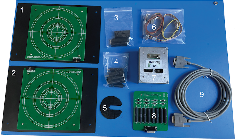
Bridge12 Active Electric Shims (AES) components
- Electrical Shims (right side, qty.: 1)
- Electrical Shims (left side, qty.: 1)
- Shim spacers (qty.: 4)
- Shim supports (qty.: 8)
- Adjustment/tightening tool (qty.: 1)
- Cables to connect shims to shim interface (qty.: 2)
- Shim interface (qty.: 1)
- Shim board adapter for Bruker BSMS shim power supply (qty.: 1)
- Cable to connect shim interface (7) to Bruker BSMS shim board adapter
Assembling the Shims
Important
Assembling the shims is best done by two people.
The electrical shims are supported between the magnet poles using a total of 8 shim supports and 4 shim spacers (shown in figure below).
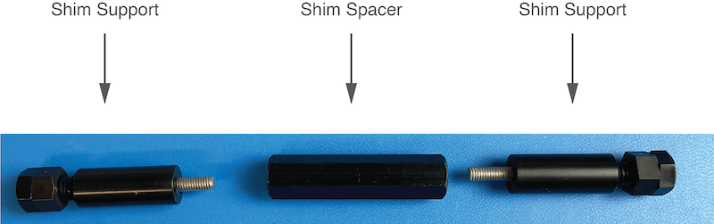
Shim Supports (left, right) and Spacer
To assemble the shims:
- Place the electrical shims (1 and 2) at the side of the magnet. The board labeled “left” should face the left magnet pole. The board labeled “right” should face the right magnet pole. The labels are located on the back of the boards.
- Place the shim spacer between the shim boards
- Screw in the shim supports on both side.
The assembly should look similar to the assembly shown in the figure below.
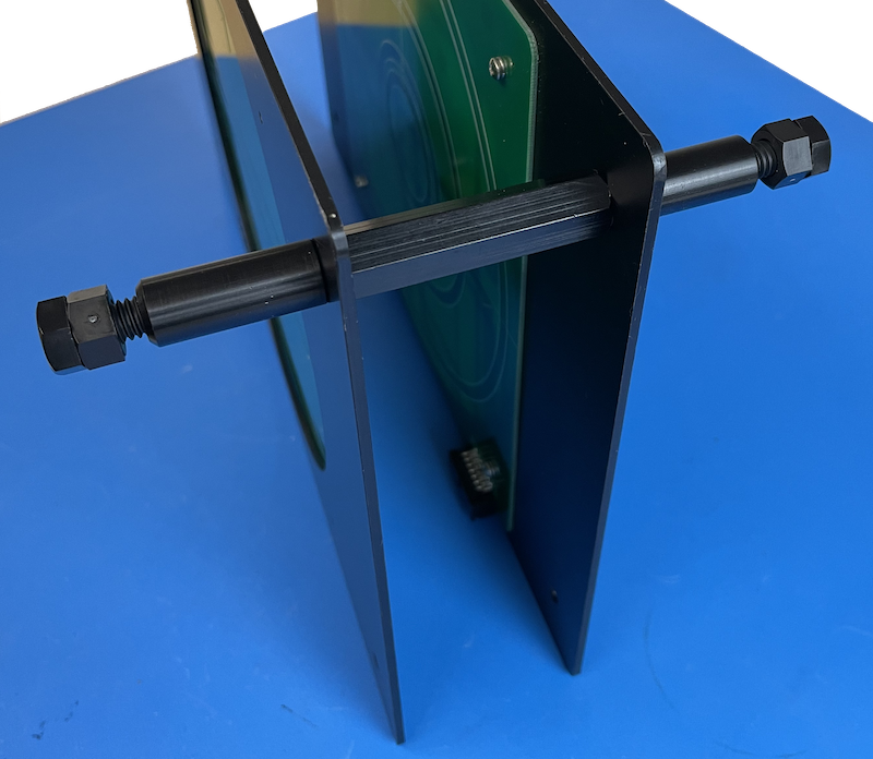
Shims with one set of supports and spacer assembled
- Repeat the previous step for all shim supports and spacers.
Alternatively, you can first assemble the shim boards using the supports and the spacers outside the magnet and place the assembled shims between the magnet poles.
Under some circumstances it is not possible to use all 8 shim supports. In this case two supports can be omitted and replaced by two screws as shown in the following image. However, make sure when locking the shims in place that their position is fully secured and that the shims won’t slide down. We don’t recommend removing more than one set of shim supports.
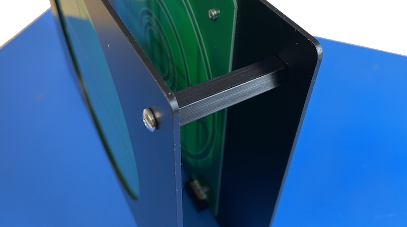
Shims with spacer only
Locking the Shims in Place
Once you have assembled the shims and placed between the magnet pole pieces, you need to lock the shims in place. Each support of the shims has an adjustment screw and a counter nut (see figure below). Before you start turn the counter nut to face the screw as shown in the figure below.
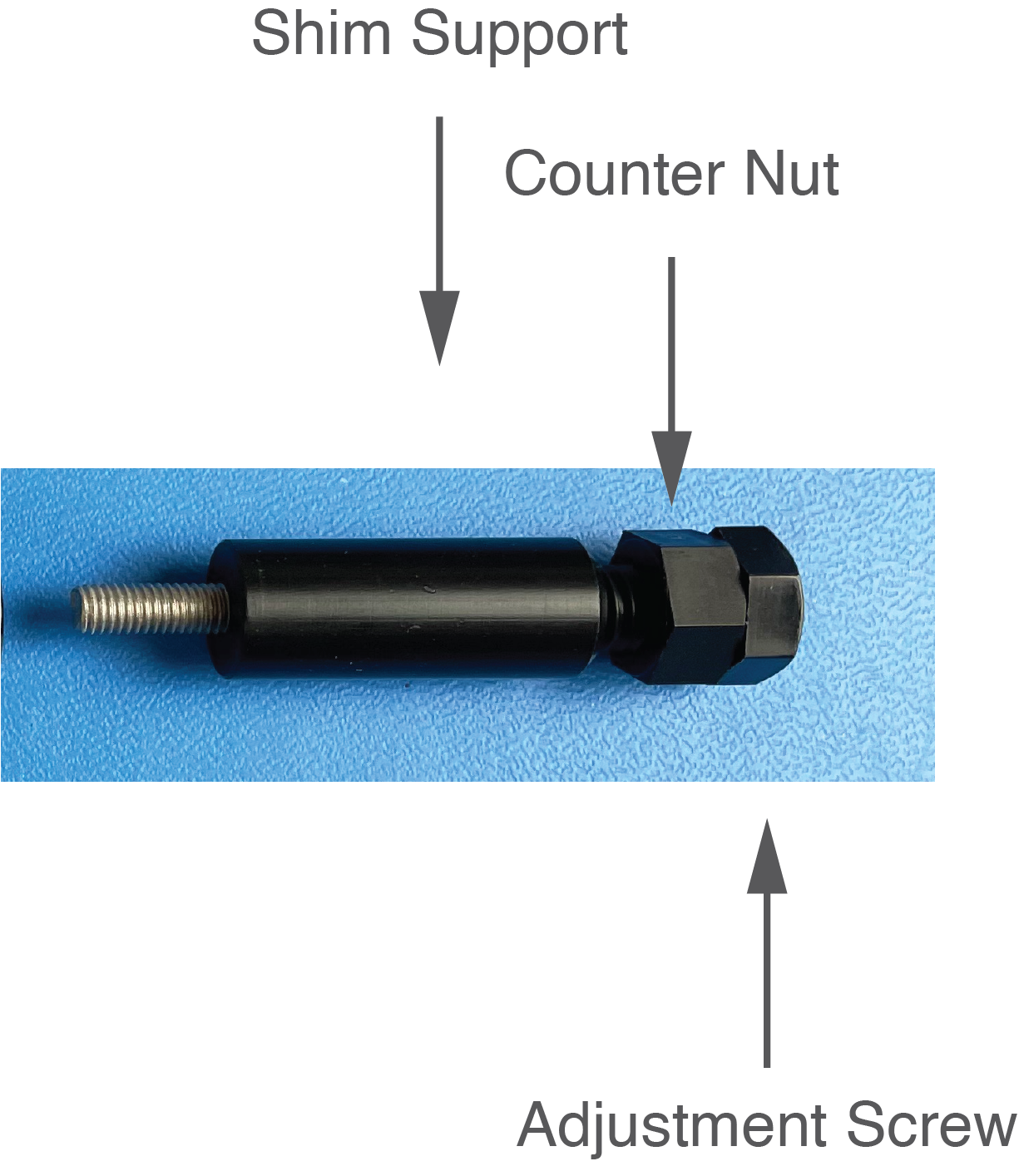
Shim Supports with adjustment screw and counter nut
To hold the shims between the magnet poles, turn the adjustment screws on all sides, until they touch the side of the magnet. Make sure the shims are centered between the pole pieces of the magnet. To turn the screws, especially when the tops of the screws are close to the sides of the magnet use the Adjustment/Tightening tool.
Once the shims are supported between the magnet poles, lock the adjustment screws by turning the counter nut until it touches the shim support. Make sure the nut is not overtightened.
The picture below shows the shims installed in an electromagnet for EPR spectroscopy.
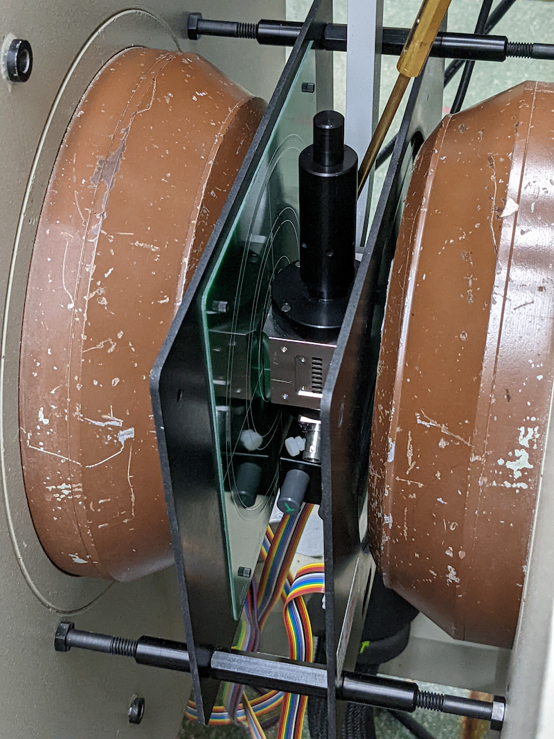
Picture of the installed shims (courtesy of Prof. Song-I Han, UCSB
Connecting the Shims
To use the shims, the following connections have to be made:
- Shims to shim interface
- Shim interface to shim power supply
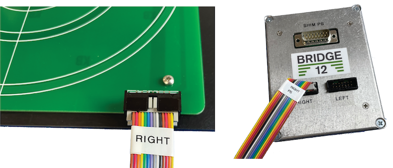
Connecting the shims to the shim interface
To connect the shims to the shim interface follow these steps:
- Starting with the shims located to the right, connect the ribbon cable marked “RIGHT” to the right shim board.
- Connect the same ribbon cable the shim interface.
- Repeat the step for the ribbon cable marked “LEFT”.
Connecting the Shims to a Lab Power Supply
The shims can be operated using any benchtop lab power supply. For convenience a multi-channel power supply can be used. Often these power supplies are not bi-polar, in which case you need to swap the leads of the respective channel if you would like to reverse the gradient (e.g. Z1 to -Z1). The power supply can be directly connected to the 15 pin sub-D connector of the shim interface.
| Pin# (sub-D) | Shim Connection | Pin# (sub-D) | Shim Connection |
|---|---|---|---|
| 1 | Z(B)0 (s) | 2 | Z(B)0 (r) |
| 3 | Z1 (s) | 4 | Z2 (r) |
| 5 | Z2 (s) | 6 | Z2 (r) |
| 7 | X (s) | 8 | X (r) |
| 9 | Y (s) | 10 | Y (r) |
| 15 | GND | Shield | GND |
| (GND - Ground, s - supply, r - return) |
Connecting the Shims to a Shim Power Supply
The shims can be operated using a shim power supply e.g. of a NMR spectrometer. The following instructions are specific to a shim power supply used in Bruker NMR consoles (courtesy to Prof. Song-I Han, UCSB).
To connect the shims to a Bruker shim power supply (e.g. BSMS/2) follow this steps:
- Connect the shim board adapter to the the shim power supply (see image below, left).
- Connect the 15 pin sub-D cable to the shim interface.
- Connect the 15 pin sub-D cable to the shim board adapter.
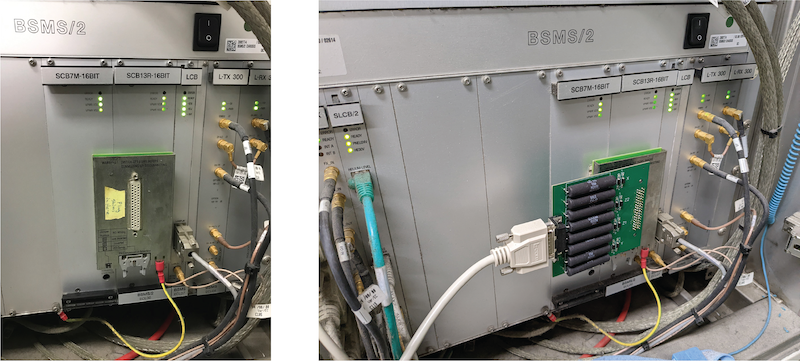
Connecting the shims to the Bruker BSMS/2 shim power supply (images courtesy Prof. Song-I Han, UCSB
Once you have made these connection, the shim can be controlled through the shim power supply.
If you need help at any step of the installation please contact Bridge12 at support@bridge12.com.