40 W Q-Band Amplifier
The Bridge12 AMP-Q40 is a 40 W solid-state microwave amplifier for Q-Band (35 GHz) pulsed EPR spectroscopy. The amplifier can fully replace a TWT amplifier and in combination with the Bridge12 QLP-1.6 probe is a great combination for pulsed dipolar EPR spectroscopy.
Note
The expected pulse length for a 180º-pulse, using a maximally overcoupled Bridge12 QLP-1.6 resonator is 16 ns.
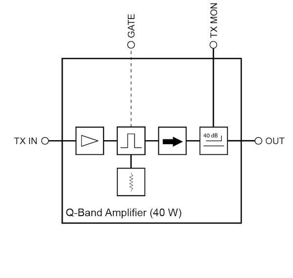
A schematic of the amplifier is shown in the figure above. The amplifier has an integrated gate, isolator, and coupler. The input connector for the amplifier is a 2.92 mm connector, while the output is a WR-28 waveguide output.
Back Panel Connections
The Bridge12 AMP-Q40 can fully replace a TWT amplifier. The following connection to the spectrometer need to be made:
- Microwave Input (TX IN): Input connection of the amplifier. This needs to be connected to the output of the EPR bridge. 2.92 mm connector.
- Microwave Output (OUT): Output connection of the amplifier. This either needs to be connected to the circulator extension (Bridge12 Q-Band spectrometer) or to the input of the EPR bridge. If you are unsure please contact Bridge12 at support@bridge12.com. If your EPR bridge requires a 2.92 mm input connection, we recommend installing a waveguide to coax adapter.
- Gate: Amplifier blanking. This gate is active HIGH and needs a trigger pulse from the EPR bridge.
- Microwave Monitor (TX MON): Monitor output of the amplifier. This is the same signal that is sent to the probe but attenuated by 40 dB. The signal can be used to monitor the microwave pulses or to characterize the amplifier performance.
- 15 Pin D-Sub Connector: Control and monitor signals of the amplifier. For a detailed pin out see tabel below.
Operating Instructions
Warning
Do not obstruct the airflow of the cooling air. This can lead to overheating of the amplifier and possible permanent damages.
Power Up Procedure
- Make sure that no microwave pulses are sent out by the EPR bridge.
- Turn on the amplifier.
- Wait a few minutes for the amplifier to warm up. For optimum, stable performance we recommend to leave the amplifier for about 20 minutes for the internal temperature to stabilize. The amplifier has an internal delay of 5 s. You need to wait at least for this time before sending the first microwave pulses.
- Apply gate and microwave pulses.
Power Down Procedure
- Make sure that no microwave pulses are sent out by the EPR bridge.
- Turn off the amplifier.
Pulse Timing
Warning
Do not Hot Switch the amplifier. Hot Switching occurs, when the blanking gate is disabled while sending a microwave pulse. This can lead to permanent damage of the internal protection circuit of the amplifier. Please see the timing diagram below.
Please refer to the timing diagram and the values below for recommended pulse timing.
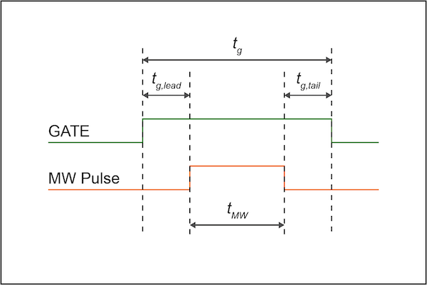
- Gate lead, tg,lead > 100 ns (200 ns recommended)
- Gate tail, tg,tail > 20 ns (50 ns recommended)
- Maximum duty cycle: 20%
- Maximum pulse length: 10 µs
- ATTENTION: DO NOT HOT SWITCH AMPLIFIER
15 Pin D-Sub Back Panel Connector
| Pin Number | Name | Function | Initial State | Description |
|---|---|---|---|---|
| 1 | Reset | Control | - | Resets PA when logic LOW is applied and released |
| 2 | Gate Disable | Control | LOW | Applying a HIGH signal disables gate of amplifier |
| 3 | Drain Disable | Control | LOW | Applying a HIGH signal disables drain of amplifier |
| 4 | RF IN Over | Indicator | LOW | Pin will be latched to HIGH when input signal is to high |
| 5 | Temp Over | Indicator | LOW | Pin will be latched to HIGH when maximum amplifier temperature is exceeded |
| 6 | Current Over | Indicator | LOW | Pin will be latched to HIGH when drain current limit is reached |
| 7 | ID Imbalance | Indicator | LOW | Pin will be latched to HIGH when an imbalance in the drain current of the combining branches occurs |
| 8 | PA Off Alarm | Indicator | LOW | Pin will be latched to HIGH when any of the protection limits are reached |
| 9 | - | not connected | - | |
| 10 | - | not connected | - | |
| 11 | - | not connected | - | |
| 12 | - | not connected | - | |
| 13 | - | not connected | - | |
| 14 | +5 V | Power Supply | +5 V | +5 V DC power supply for reference. Mac. 400 mA available |
| 15 | GND | Ground | GND | Electrical ground |