DAQ Control
Please make sure the control software for the DAQ interface is installed. If you haven’t done so, you can download it here.
Connecting to the DAQ Interface
To connect to the DAQ interface follow these steps:
- Make sure the X-Band IF USB interface is connected to the host computer.
- Start Kipling
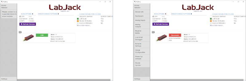
- In the GUI click the green USB button (see figure above, left). The USB button will turn red, indicating that Kipling is connected to the DAQ interface (see figure above, right).
Digital Input/Output Control
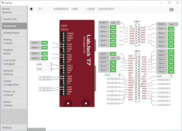
To control the digital input/output lines click on the menu item Dashboard (see figure above). Each of the lines can be configured as an input or output by selecting the control from the drop-down menu. If the line is configured as an input the indicator to the left will show whether the line is logic high or low. If the line is configured as an output, the status can be changed by selecting the desired status from the drop-down menu.
Below is a list of the different digital channels used by the X-Band IF system.
Pulse Forming Unit (PFU)
| Bit Name | Function |
|---|---|
| CIO0 | AWG LO select for PFU. 0 - Internal synthesizer (LO1), 1 - AUX LO, auxillary LO input on back panel |
Receiver (RCVR)
| Bit Name | Function |
|---|---|
| CIO1 | Enable/Disable video amplifiers. 0 - disabled, 1 - enabled |
| FIO4 | Microwave signal amplifier, 0 - disabled, 1 - enabled +20 dB gain |
Analog Output Control
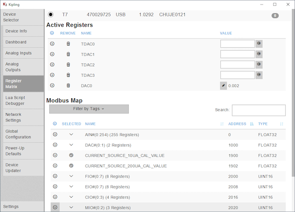
The value of the various analog outputs can be controlled from the Register Matrix panel. The values for TDAC0 - TDAC3 can be set between -10 and +10 V, with a resolution of 16 bit.
Below is a list of the different analog channels used by the X-Band IF system.
Receiver
| Bit Name | Function |
|---|---|
| TDAC0 | Video amplifier gain control (I channel), value from -10 to 10 V, -10 V - 30 dB gain, 10 V - 65 dB gain |
| TDAC1 | Video amplifier gain control (Q channel), value from -10 to 10 V, -10 V - 30 dB gain, 10 V - 65 dB gain |
| TDAC2 | LO level receiver, value from -10 to 10 V, -10 V - 0 attenuation, full power on LO of IQ mixer (RCVR), 10 V - 30 dB attenuation, lowest power on LO of IQ mixer (RCVR) |
Miscellaneous Other Controls
The X-Band IF system has several spare digital and analog input and output lines connected to the IO and EXT connector located on the back panel. These lines can be configured by the user.
Note
For most sub-D connectors the pin number is either printed on the front either at the pin (male connector) or the receptacle (female connector).
EXT Connector (9 pin sub-D, back panel)
The external connector is most commonly used to control an extension to the X-IF system, such as a frequency extension.
All lines are configured as outputs in SpecMan.
| Pin Number sub-D |
Bit Name (LabJack) |
SpecMan Variable |
Function | Reserved For |
|---|---|---|---|---|
| 1 | EIO0 | Ext1 | DAQ bit EIO0, can be configured as input and output, TTL level | |
| 2 | EIO2 | Ext3 | DAQ bit EIO2, can be configured as input and output, TTL level | |
| 3 | EIO4 | Ext5 | DAQ bit EIO4, can be configured as input and output, TTL level | |
| 4 | EIO6 | Ext6 | DAQ bit EIO6, can be configured as input and output, TTL level | |
| 5 | GND | n/a | System GND | |
| 6 | EIO1 | Ext2 | DAQ bit EIO1, can be configured as input and output, TTL level | |
| 7 | EIO3 | Ext4 | DAQ bit EIO3, can be configured as input and output, TTL level | |
| 8 | EIO5 | Ext6 | DAQ bit EIO5, can be configured as input and output, TTL level | |
| 9 | EIO7 | Ext8 | DAQ bit EIO7, can be configured as input and output, TTL level |
IO Connector (9 pin sub-D, back panel)
| Pin Number sub-D |
Bit Name (LabJack) |
SpecMan Variable |
Function | Reserved For (SpecMan) |
|---|---|---|---|---|
| 1 | MIO0 | IO1 | DAQ bit MIO 0, can be configured as input and output (TTL level) | Enable/disable tune mode |
| 2 | MIO2 | IO3 | DAQ bit MIO 2, can be configured as input and output (TTL level) | |
| 3 | DAC1 | DAC1 | DAQ bit DAC 1. This is an analog output. The value can be changed between 0 and 5 V. The output is controlled from the Dashboard menu | |
| 4 | AIN1 | DAQ bit AIN1, analog input range ±10V, ±1V, ±0.1V and ±0.01V | ||
| 5 | GND | n/a | System GND | |
| 6 | MIO1 | IO2 | DAQ bit MIO 1, can be configured as input and output (TTL level) | Enable/disable external high-power amplifier |
| 7 | TDAC3 | TDAC 3, values (set in software) -10 to 10 V, output is 0 to 10 V, 14 bit resolution | ||
| 8 | AIN0 | DAQ bit AIN0, analog input range ±10V, ±1V, ±0.1V and ±0.01V | ||
| 9 | Vs | 5 V supply voltage |
VCA Connector (SMA, back panel)
| Bit Name | Function |
|---|---|
| DAC0 | VCA control (back panel). This is an analog output. The value can be changed between 0 and 5 V. The output is controlled from the Dashboard menu, value 0 to 5 V |