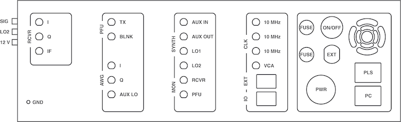
X-Band IF Backpanel Connections
Below, please find a list and description of the backpanel connectors of the X-Band IF system. Please refer to the figure below for the location of connections.
Warning
Whether a connector is used for an input or output signal is labeled in the table below. Please make sure the user makes the correct connections. Wrong connections can lead to permanent damages of the system.
RF Connections
Please refer to the table below for a description of the back panel connectors of the X-Band IF system. The function (I/O - input/output) of the connector is indicated in the second column.
Information
Make sure all connections to the back panel connectors are properly tighten. SMA connections should be tightened using a torque wrench (recommended torque 10 Nm).
Side Panel
| Connector | I/O | Type | Description |
|---|---|---|---|
| SIG | I | SMA | Input signal for the receiver. |
| LO2 | O | SMA | LO2 output of the microwave synthesizer (channel B) |
Back Panel
Receiver (RCVR)
| Connector | I/O | Type | Description |
|---|---|---|---|
| RCVR I | O | SMA | I channel of the quadrature receiver channel. This is typically referred to as the real signal of the detected EPR signal. |
| RCVR Q | O | SMA | Q channel of the quadrature receiver channel. This is typically referred to as the imaginary signal of the detected EPR signal. |
| RCVR IF | I | SMA | IF input of the RCVR. For X-Band operation, this should be connected to the LO1 output of the microwave synthesizer (channel A). Suggested Cable |
Pulse Forming Unit (PFU) and AWG Input
| Connector | I/O | Type | Description |
|---|---|---|---|
| PFU TX | O | SMA | Output of the PFU. This signal is typically routed to the high-power amplifier or the active multiplier chain (AMC) in high-field/high-frequency EPR spectrometers. |
| PFU BLNK | I | SMA | Blanking gate of the PFU. TTL logic. Active high. This signal has to be connected to the pulse programmer. |
| AWG I | I | SMA | I channel input of the PFU. This signal needs to be connected to the output channel of the AWG. |
| AWG Q | I | SMA | Q Channel input of the PFU. This signal needs to be connected to the output channel of the AWG. |
| AWG AUX | I | SMA | Auxillary input of the IQ mixer LO channel. |
Synthesizer and Monitors
| Connector | I/O | Type | Description |
|---|---|---|---|
| AUX IN | I | SMA | Auxillary microwave signal input. This signal is combined with the microwave signal generated by the IQ mixer of the PFU and allows the user to inject an additional, user-created microwave signal. |
| AUX OUT | O | SMA | LO signal of the LO input for the IQ mixer of the PFU. This signal is similar to LO1. |
| LO1 | O | SMA | LO1 signal of the X-Band IF system (channel A of the synthesizer). |
| LO2 | O | SMA | LO2 signal of the X-Band IF system (channel B of the synthesizer). |
| RCVR | O | SMA | Receiver input monitor. |
| PFU | O | SMA | PFU output monitor. |
Reference Clock and External IO
| Connector | I/O | Type | Description |
|---|---|---|---|
| 10 MHZ | O | SMA | Oven-controlled 10 MHz reference clock signal. Output power level 10 dBm. |
| VCA | O | SMA | 0 - 5 V DC signal. The output level of this signal can be controlled through the software. This signal is typically used for the Voltage Controlled Attenuator (VCA) of a high-frequency AMC. |
| EXT | O | D-Sub | 9 pin d-sub connector. Pin Out |
| IO | O | D-Sub | 9 pin d-sub connector. Pin Out |
Other Connections
Side Panel
| Connector | I/O | Type | Description |
|---|---|---|---|
| 12 V | O | LEMO | 12 V output. This supply voltage can be used to power up external equipment. Do not exceed 200 mA. Mating Connector |
Other Connectors
| Connector | I/O | Type | Description |
|---|---|---|---|
| EXT PWR | O | M12 | Power supply e.g. for a frequency extension. Available voltages: -12 V, -5 V, 5 V, 12 V, 15 V |
| PWR | I | Amphenol | Power inlet for the X-Band IF system. Please only use the power supply supplied with the system to avoid permanent damages. |
| PLS | I/O | USB | USB connection from the X-Band IF to the pulse programmer. This USB port is connected to the internal USB hub of the X-Band IF system. |
| PC | I/O | USB | USB connection to remote PC. |
| GND | n/a | STUD | A ground (GND) post is located in the lower left corner of the back panel. |
Warning
Only use the power adapter that came with the X-Band IF system to power up the instrument.
Failure to use the correct power adapter can lead to permanent damage of the system.
If you are unsure about the power adapter, please contact Bridge12 at support@bridge12.com