Connecting the NMR Probe
How to Connect the NMR Probe to the Bridge12 SCN Hardware
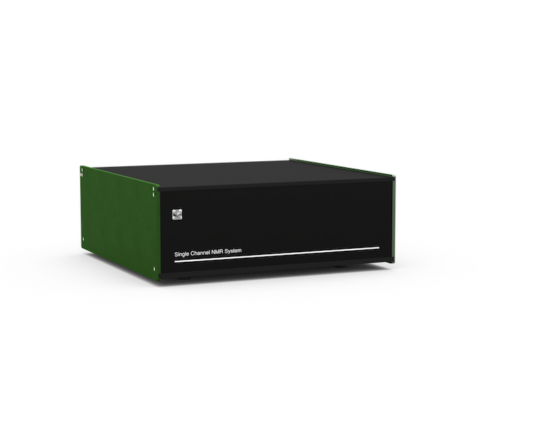
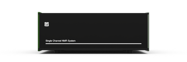
Bridge12 SCN Front Panel Connectors
The NMR probe is connected to the Bridge12 SCN using the SMA connector located on the front panel of the system.
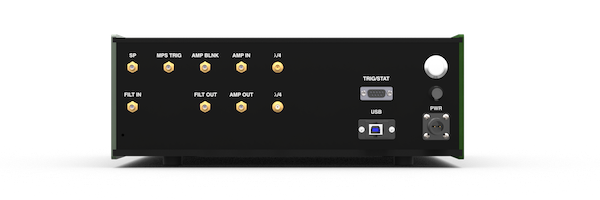
Bridge12 SCN Back Panel Connectors
Most connections for the Bridge12 SCN are located on the back panel.
| Connector Label | Style | Description |
|---|---|---|
| USB | USB-B | USB connection to spectrometer computer |
| PWR | Circular | System power connection. The input voltage for the system is 24 VDC, 1.25 A. To power the system, please use the power (desktop) adapter that was delivered with the system. |
| FILT IN FILT OUT |
SMA(f) | Receiver input filter (bandpass). The bandpass filter is used to reduce the noise in the system. By default the Bridge12 SCN comes with a bandpass filter for 1H NMR spectroscopy. If you like to operate the system at a different Larmor frequency the filter has to be replaced with a bandpass filter for the desired frequency. Additional filters can be found on the MiniCircuits webpage. |
| λ/4 | SMA(f) | Connection for the λ/4 cable. The Bridge12 SCN uses a passive Transmit/Receive (T/R) switch to protect the receiver. For this an appropriate λ/4 needs to be conneted to the two connectors. By default the system comes with a λ/4 cable for 1H NMR spectroscopy. If you wish to study other nuclei you need to replace the 1H with a cable with a different length. Instructions to make your own cable can be found on the webpage for the OpenTRSwitch or contact Bridge12 at support@bridge12.com. |
| AMP IN | SMA(f) | External amplifier input. |
| AMP OUT | SMA(f) | External amplifier output. |
| AMP BLNK | SMA(f) | Blanking gate for external amplifier. The blanking gate is active low. If you have questions about how to connect an external amplifier please contact Bridge12 at support@bridge12.com |
| MPS TRIG | SMA(f) | Trigger pulse for the Bridge12 MPS to modulate the output power. The trigger is active high. |
| SP | SMA(f) | Not used. |
| TRIG/STAT | D-Sub (f) | Auxiliary connector. Pinout: 1: 10 MHz reference for external use, 2, 3: Not connected, 4: Hardware trigger, 5: Hardware reset, 6, 7, 8, 9: GND |
A fuse holder is located on the back panel of the SCN. If necessary, the user can replace the fuse. The dimensions are 5x20mm and the fuse should have a rating of 1.25A.
To power the SCN connect the external power supply to the PWR connection. then connect the USB-C port to a PC. Connect the input of a bandpass filter corresponding to your NMR frequency to the ‘FILT OUT’ connector and the output of the bandpass filter to the ‘FILT IN’ connector. Connect a \(\lambda\)/4 filter (e.g. a cable with the correct length) for your NMR frequency to the \(\lambda\)/4 connectors.
Not sure if we need this right now.
How to Connect the NMR Probe to the Bridge12 SCN Hardware
Connecting an External Amplifier to the Bridge12 SCN Hardware
Using an External Trigger