Please read the documentation carefully to avoid any damages to the Bridge12 probes for EPR/DNP spectroscopy.
Welcome to the online documentation for our probes for EPR and DNP spectroscopy. Bridge12 stopped distributing paper manuals with their probes to keep the documentation always up to date. If you have questions, or suggestions for edits please contact us at info@bridge12.com.
1 - Q-Band QLP (EPR)
Online documentation of the Bridge12 QLP probe
Welcome to the online documentation of the Bridge12 QLP probe for pulsed dipolar spectroscopy. Bridge12 does not distribute paper manuals with their probes to keep the documentation always up to date. If you have questions, or suggestions for edits please contact us at info@bridge12.com.
Pulsed Electron Paramagnetic Resonance (EPR) spectroscopy using high-power microwave pulses or arbitrary waveform generated (AWG) broadband pulses require a large resonator bandwidth (low resonator Q) to avoid distortion of the pulse shape. However, large resonator bandwidth often comes at the cost of a reduced microwave conversion factor. Loop-Gap Resonators (LGR) combine all these desired features together with an excellent field homogeneity across the sample. This is especially important when using AWG generated broadband pulses.
At the heart of the probe is a Loop-Gap Resonator (LGR), with a large conversion factor, and an homogenous B1e microwave field across the entire sample volume to improve the performance of pulsed EPR experiments. The resonator is the ideal choice when using pulses generated by an Arbitrary Waveform Generator (AWG).
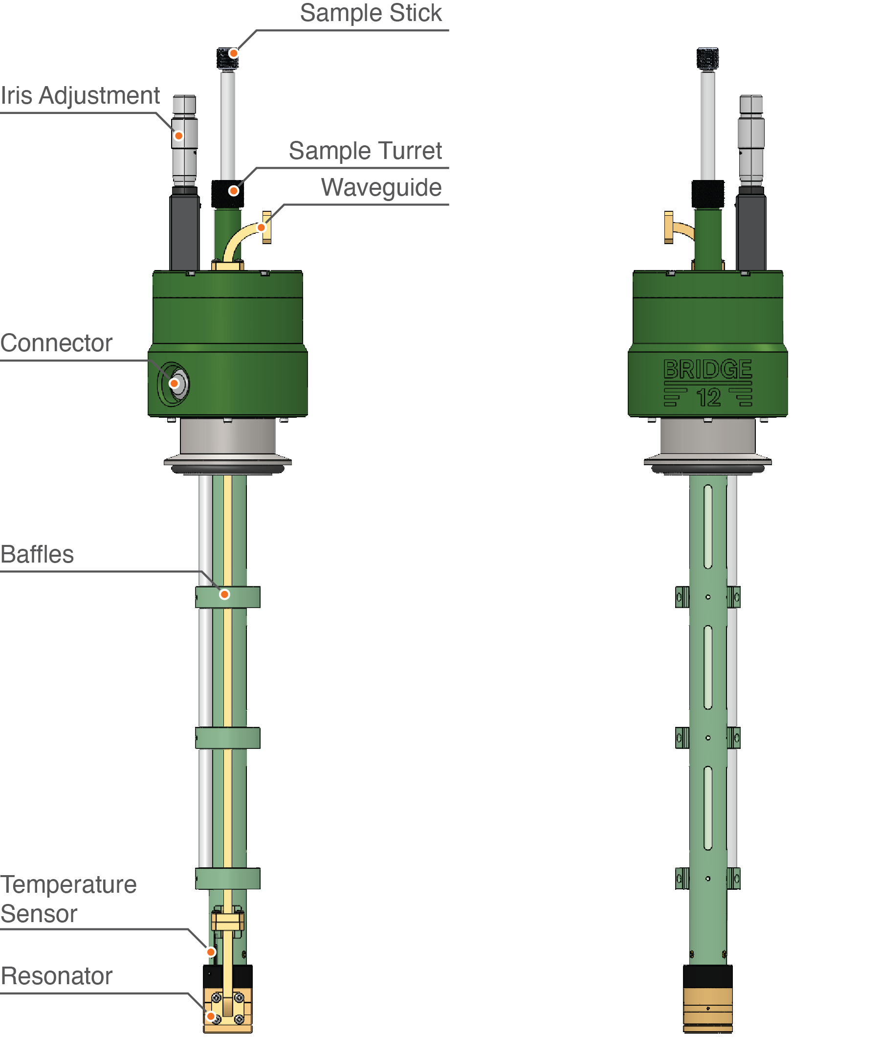
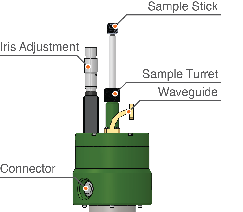
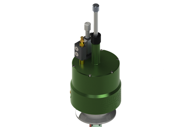
Bridge12 QLP Overview
An overview of the Bridge12 QLP probe is given in the figure shown above. For low-temperature measurements, the probe can be operated inside a cryostat. The Bridge12 QLP is compatible with commonly used cyrostats, such as the Oxford Instruments cryostat model CF935.
The main features of the probe are:
The resonator
Integrated temperature sensor
Baffles along the length of the probe
Electrical connector to connect the temperature sensor to a controller
The sample holder turret
WR-28 Waveguide connection
Iris adjustment
Optical Access
Optical access to the sample location for e.g. light/laser irradiation is possible in several different ways:
Through the sample holder/stick (for fiber access only).
Free-space access through the bottom of the resonator.
Free-space access perpendicular to the sample axis (please inquire with Bridge12 about this option).
If you like to use an optical fiber to irradiate the sample using the sample holder/stick (option 1), please contact Bridge12 at info@bridge12.com for further information.
Temperature Sensor
The Bridge12 QLP probe has a built-in, calibrated Cernox temperature sensor. The connector is located on the top of the probe. Please use the cable that came with the probe to connect the probe to the temperature controller.
More information about the pin-out can be found in the section Temperature Sensor.
A rectangular waveguide port (WR-28) is located at the top of the probe. The waveguide flange is a UG-599/U with 4 tapped holes, screw size #4-40. This waveguide port is used to connect the QLP probe to the EPR spectrometer. The probe waveguide has an integrated vacuum window to seal the probe to the atmosphere, when operating the probe at cryogenic temperatures.
Warning
Do not drop any screws or washers into the waveguide port. This could potentially damage the vacuum window located inside the waveguide.
If parts are accidentally dropped into the waveguide, do not use any sharp objects to retrieve the part. Instead, flip the probe over and gently shake the probe to remove the dropped item.
If a part got stuck inside the waveguide and you are not able to retrieve it, do not connect the probe to the spectrometer, and contact Bridge12 at info@bridge12.com.
Connecting the Probe to the Spectrometer
Important
Please make yourself familiar with the instructions below before attempting to install the probe. At no point should you use any force during the installation process. In general, all threads, screws, etc. are imperial size, not metric. Please use the appropriate tools to fasten all screws.
Please follow these steps to connect the probe to the spectrometer:
First time installation: Remove Kapton tape from waveguide flange (for shipping the waveguide port of the probe is protected by a strip of Kapton tape).
Place probe inside cryostat. If you don’t use a cryostat, place probe in the appropriate support structure.
Turn/orient the probe so the waveguide port is located to the left. The waveguide port should be on the side that provides the shortest distance to the EPR bridge. Typically, the EPR bridge is located to the left of the probe.
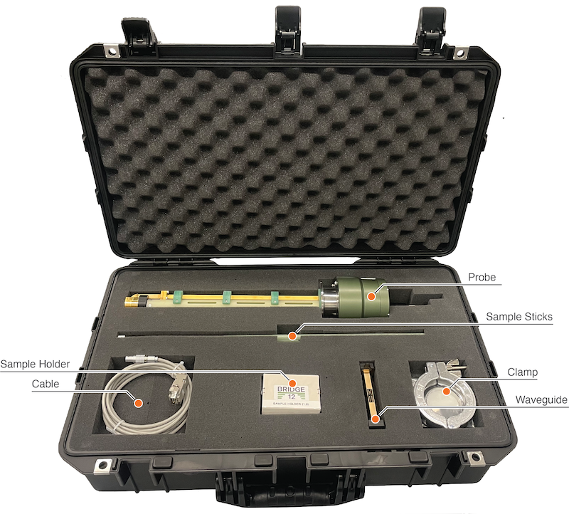
To connect the probe to your EPR instrument, the probe comes with additional waveguide components:
WR-28 straight waveguide section, 4 in. length
WR-28 E-bend, 1.5 in.
#4-40 screws, 3/8 in.
In addition to these parts, please also use the flexible WR-28 waveguide section provided with the EPR instrument to connect the probe to the spectrometer.
Every EPR instrument is slightly different. Here are different scenarios to connect the probe.
Place the E-band on top of the probe, and use the flexible waveguide to connect the probe to the spectrometer.
First add the straight section to the top of the probe and cover the rest of the distance with the flexible waveguide.
Caution
When connecting two waveguide sections, always orient the waveguides so that the long section of both waveguides are parallel to each other.
Once the waveguide is connected, connect the temperature sensor to the temperature controller.
For the Bridge12 QLP-1.6 mm please use a sample capillary with a maximum OD of 1.6 mm. A link to the sample tube vendor can be found on the Cosumables Page.
Mounting the Sample
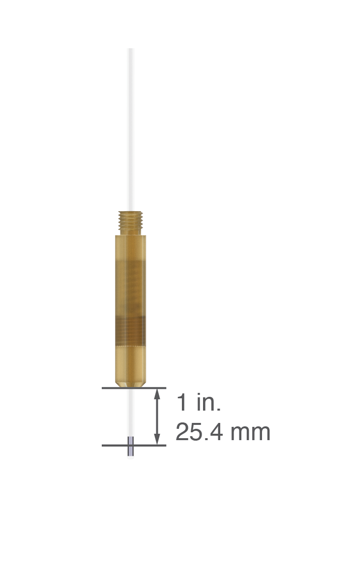
Please follow the instructions for using the sample stick to mount the EPR sample to the Sample Stick. In general, the distance between the center of the sample and the bottom of the sample holder should be about 1 inch (25.4 mm) (see figure below).
Recommended distance between the center of the sample and the bottom of the sample holder
Inserting the Sample Stick
To insert the sample stick into the probe follow these instructions:
Note
Please keep in mind that these instructions can differ, depending on the type and make of the low-temperature cryostat.
If the cryostat is cooled down, stop the cooling. Wait for the pressure inside the cryostat to reach atmospheric pressure.
If using a purge gas, switch on a slow stream of purge gas.
Loosen the nut at the top of the sample turret (see figure above). Depending on the probe the nut may be made from brass, stainless steel, or anodized aluminum. Typically, just loosen the nut should be sufficient, it is not necessary to completely remove the nut.
Pull out previous sample stick or blind plug. If the purge gas is running, there should be no ambient air entering the cold space of the cryostat.
Insert the new sample stick (or blind plug).
Push sample stick all the way to the bottom. If the distance between the center of the sample and the bottom of the sample holder is 1 inch, the bottom of the sample holder will rest on top of the resonator.
Tighten the nut at the top of the sample turret. Please don’t use any tools to tighten the nut.
Start the cooling and wait for the temperature to settle before attempting to tune the resonator.
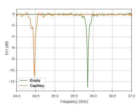
The frequency of the empty resonator is typically between 35.5 and 36 GHz. This may be outside of the normal operating frequency of a typical EPR spectrometer, however, inserting the sample into the resonator, this will shift the frequency to lower values (dielectric loading) as shown in the figure below. The amount of the frequency shift depends on the size and material of the sample capillary and the nature of the sample (e.g. polymer at room temperature, frozen aqueous solution, etc.). Please see the section Consumables for the recommended sample size.
QLP Frequency Shift
Due to the nature of the resonator, the resonance frequency will not noticeably change when cooling down to cryogenic temperatures.
Important
If you have already samples that are loaded into a smaller capillaries, we recommend placing the existing capillary into the WG-221T-RB sample tube to shift the resonator frequency to the correct regime.
Iris Coupling
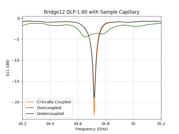
The microwave coupling to the resonator is adjusted using an iris. The iris can be mechanically controlled using a micrometer screw head, located at the top of the probe (Iris Adjustment, see figure above). By turning the micrometer screw, the iris is moved up and down and the resonator coupling can be changed from undercoupled to critically coupled to overcoupled as shown in the figure below.
QLP Iris Adjustment
Typical Q values and conversion factors for the overcoupled and critically coupled resonator:
Parameter
Value
Microwave Conversion Factor (critically coupled)
> 12 G/sqrt(W)
Bandwidth (critcially coupled)
Q ~ 300 - 400 (85 - 113 MHz)
Microwave Conversion Factor (overcoupled)
> 5 G/sqrt(W)
Bandwidth (critcially coupled)
Q < 85 (> 400 MHz)
To achieve the largest resonator bandwidth, the iris should be at its highest position. However, in some circumstances it may be beneficial to lower the iris to increase the B1e field strength, at the expense of the resonator bandwidth.
Warning
Critically coupling the resonator can lead to significant probe ring-down, with power reflected back to the EPR spectrometer exceeding safe levels. When attempting to critically couple the resonator, make sure to start a low and safe level of excitation power.
Adjusting the Iris Coupling
To adjust the coupling of the resonator, follow these steps:
Lower the micrometer iris adjustment to the minimum position (down) by turning the micrometer head clockwise. Once the iris is in its lowest position, the resonator will be critically coupled. Do not force the iris mechanism, especially at cryogenic temperatures.
Change the spectrometer frequency so the resonator dip is all the way to the right. Inserting the sample will cause the frequency to shift to a lower level.
Insert the sample holder into the resonator.
While inserting the sample, follow the tuning dip. If necessary, adjust the spectrometer frequency, so the dip is not moving outside the observable region.
Make sure the sample stick is lowered all the way into the probe.
Raise the iris by turning the micrometer screw counter clockwise until the desired bandwidth is obtained.
Raising the iris (turning the micrometer screw counter clockwise) will lower the Q-value and increase the resonator bandwidth (see figure above) without changing the resonator frequency.
References to pulsed dipolar EPR spectroscopy and articles citing the QLP probe
References Specific to the Bridge12 QLP Probe
List of links to scientific publications in which the Bridge12 QLP resonator was used:
Hasanbasri, Zikri, Nicholas A. Moriglioni, and Sunil Saxena. “Efficient Sampling of Molecular Orientations for Cu(II)-Based DEER on Protein Labels.” Physical Chemistry Chemical Physics, March 15, 2023. https://doi.org/10.1039/D3CP00404J.
General References
The field of pulsed dipolar spectroscopy is rapidly evolving. Below, find some general literature references for dipolar spectroscopy and the required instrumentation.
Reviews/Books:
Goldfarb, Daniella. “Pulse EPR in Biological Systems – Beyond the Expert’s Courtyard.” Journal of Magnetic Resonance 306 (September 2019): 102–8. https://doi.org/10.1016/j.jmr.2019.07.038.
Tsvetkov, Yuri D., Michael Bowman, and Yuri Grishin. Pulsed Electron–Electron Double Resonance: Nanoscale Distance Measurement in the Biological, Materials and Chemical Sciences. Springer International Publishing, 2019. https://doi.org/10.1007/978-3-030-05372-7.
Borbat, Petr P., and Jack H. Freed. “Multiple-Quantum ESR and Distance Measurements.” Chemical Physics Letters 313, no. 1–2 (November 1999): 145–54. https://doi.org/10.1016/S0009-2614(99)00972-0.
PELDOR:
Milov, A. D., A. B. Ponomarev, and Yu. D. Tsvetkov. “Electron-Electron Double Resonance in Electron Spin Echo: Model Biradical Systems and the Sensitized Photolysis of Decalin.” Chemical Physics Letters 110, no. 1 (September 14, 1984): 67–72. https://doi.org/10.1016/0009-2614(84)80148-7.
SIFTER:
Jeschke, G., M. Pannier, A. Godt, and H. W. Spiess. “Dipolar Spectroscopy and Spin Alignment in Electron Paramagnetic Resonance.” Chemical Physics Letters 331, no. 2 (December 1, 2000): 243–52. https://doi.org/10.1016/S0009-2614(00)01171-4.
Q-Band LGR Resonators
Denysenkov, Vasyl, Philipp van Os, and Thomas F. Prisner. “Q-Band Loop-Gap Resonator for EPR Applications with Broadband-Shaped Pulses.” Applied Magnetic Resonance 48 (December 1, 2017): 1263–72. https://doi.org/10.1007/s00723-017-0930-9.
Tschaggelar, Rene, Frauke D. Breitgoff, Oliver Oberhänsli, Mian Qi, Adelheid Godt, and Gunnar Jeschke. “High-Bandwidth Q-Band EPR Resonators.” Applied Magnetic Resonance 48 (December 1, 2017): 1273–1300. https://doi.org/10.1007/s00723-017-0956-z
RIDME:
Kulik, L. V., S. A. Dzuba, I. A. Grigoryev, and Yu. D. Tsvetkov. “Electron Dipole–Dipole Interaction in ESEEM of Nitroxide Biradicals.” Chemical Physics Letters 343, no. 3 (August 3, 2001): 315–24. https://doi.org/10.1016/S0009-2614(01)00721-7.
Milikisyants, Sergey, Francesco Scarpelli, Michelina G. Finiguerra, Marcellus Ubbink, and Martina Huber. “A Pulsed EPR Method to Determine Distances between Paramagnetic Centers with Strong Spectral Anisotropy and Radicals: The Dead-Time Free RIDME Sequence.” Journal of Magnetic Resonance 201, no. 1 (November 2009): 48–56. https://doi.org/10.1016/j.jmr.2009.08.008.
Abdullin, Dinar, Fraser Duthie, Andreas Meyer, Elisa S. Müller, Gregor Hagelueken, and Olav Schiemann. “Comparison of PELDOR and RIDME for Distance Measurements between Nitroxides and Low-Spin Fe(III) Ions.” The Journal of Physical Chemistry B 119, no. 43 (October 29, 2015): 13534–42. https://doi.org/10.1021/acs.jpcb.5b02118.
Welcome to the online documentation of the Bridge12 XLP probe for pulsed EPR and ODNP spectroscopy. Bridge12 does not distribute paper manuals with their probes to keep the documentation always up to date. If you have questions, or suggestions for edits please contact us at info@bridge12.com.
The Bridge12 XLP(O) probe is an EPR probe designed for pulsed X-Band (~ 9.5 GHz) EPR spectroscopy based on a loop gap resonator. The probe is optimized for pulsed EPR experiments, which require a large resonator bandwidth and high microwave conversion factors.
This X-Band probe is available in two different configurations:
Both configurations are based on a Loop-Gap Resonator (LGR). When completely overcoupled, the resonator has a large bandwidth, and the high microwave conversion factor guaranties large B1e fields. This makes the XLP resonator the ideal choice for pulsed EPR experiments that require a large excitation bandwidths.
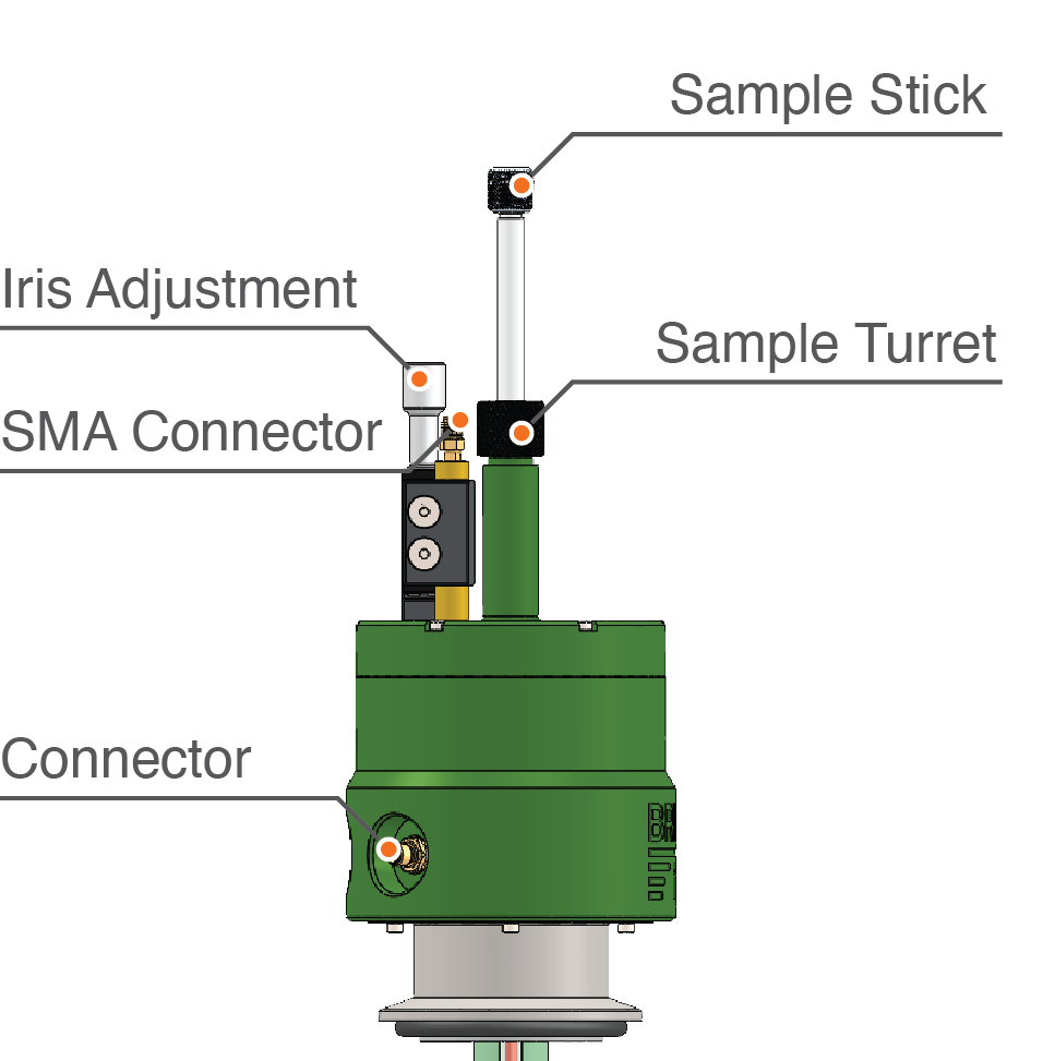
Bridge12 XLP Overview
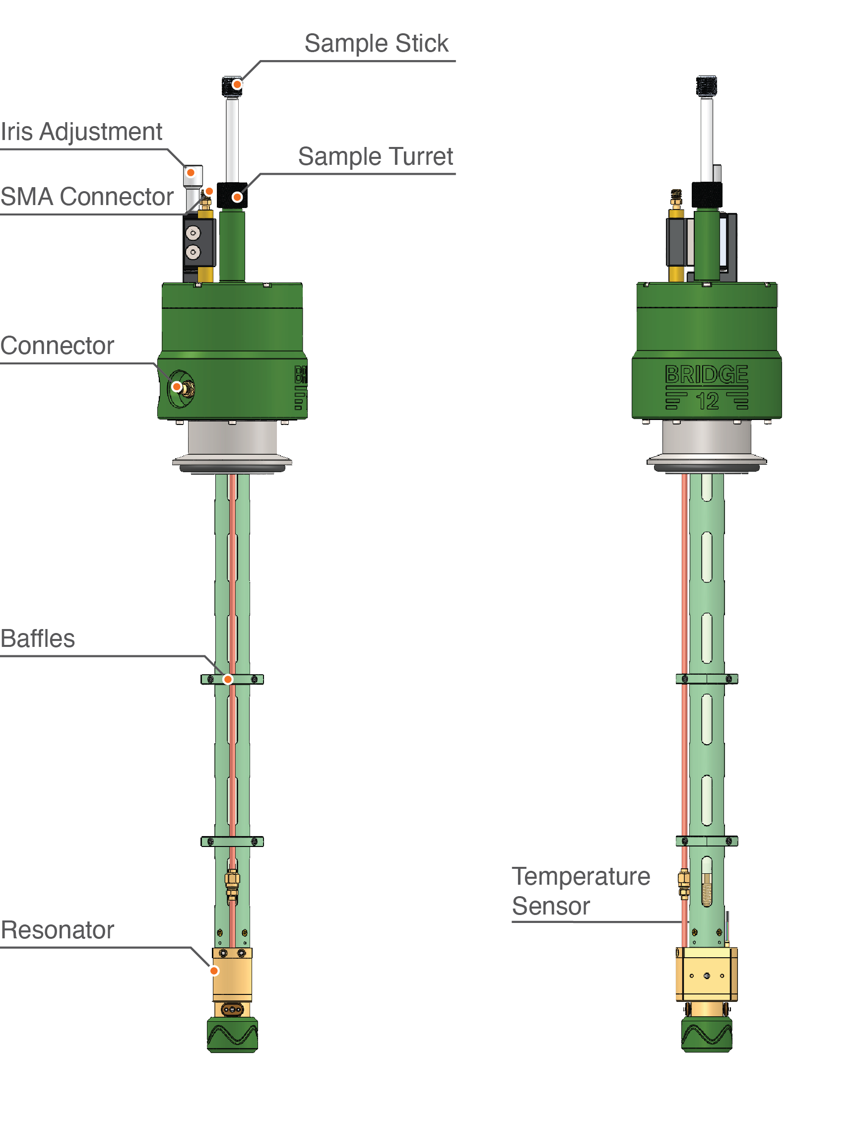
An overview of the Bridge12 XLP probe is shown in the figure shown above. For low-temperature measurements, the probe can be operated inside a cryostat. The Bridge12 XLP is compatible with commonly used cyrostats, such as the Oxford Instruments cryostat model CF935.
The main features of the probe are:
The resonator
Integrated temperature sensor
Baffles along the length of the probe
Electrical connector to connect the temperature sensor to a controller
SMA connector
Sample turret with sample stick
Iris adjustment
Optical Access
Optical access to the sample location for e.g. light/laser irradiation is possible in several different ways:
Through the sample holder/stick (for fiber access only).
Free-space access perpendicular to the sample axis (please inquire with Bridge12 about this option).
If you like to use an optical fiber to irradiate the sample using the sample holder/stick (option 1), please contact Bridge12 at info@bridge12.com for further information.
Temperature Sensor
The Bridge12 XLP probe has a built-in, calibrated Cernox temperature sensor. The connector is located at the back of the probe. Please use the cable that came with the probe to connect the probe to the temperature controller.
More information about the pin-out can be found in the section Temperature Sensor.
Please make yourself familiar with the instructions below before attempting to install the probe. At no point should you use any force during the installation process. In general, all threads, screws, etc. are imperial size, not metric. Please use the appropriate tools to fasten screws.
Bridge12 XLP Overview
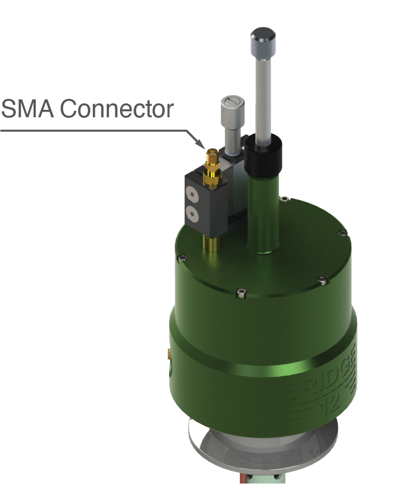
The Bridge12 XLP has a single SMA port to connect the probe to the spectrometer (see figure above). The SMA port is located at the top of the probe. Since the iris coupling is adjusting by moving the coupling loop inside the resonator up and down, we suggest using a flexible SMA cable between the bridge and the probe.
To connect the probe to the spectrometer follow these steps:
Remove plastic cover from SMA connector (typically used for shipping or long-term storage of the probe).
Place probe inside cryostat. If you don’t use a cryostat, place probe in the appropriate support structure.
Turn/orient the probe so the SMA connector and translation stage is pointing to the back and the Bridge12 logo is facing the front. Typically, the EPR bridge is located on the left.
Connect a flexible SMA cable between the EPR bridge and the probe. If your EPR bridge was a WR-90 waveguide port (this will be the case with most older bridges) you first need to connect a WR-90 to SMA adapter.
Tighten the SMA connections with your fingers. Ideally, you should use an SMA torque wrench. Do not use pliers to tighten the connection.
Connect the temperature sensor to the temperature controller.
Warning
Do not use force to tighten the SMA connector. Do not use pliers or regular wrenches to tighten the SMA connection. We recommend using a torque wrench when tightening SMA connections. Torque wrenches for SMA connections are available from DigiKey or Mouser. If you don’t have a torque wrench available please just use your fingers to tighten the connection. Using the wrong tools can lead to permanent damages of the probe.
The BRidge12 XLP probe can except samples up to a maximum OD of 3.0 mm. Vendor links to sample tubes and capillaries can be found on the Cosumables Page.
Mounting the Sample
Please follow the instructions for using the sample stick to mount the EPR sample to the Sample Stick. In general, the distance between the center of the sample and the bottom of the sample holder should be about 1 inch (25.4 mm) (see figure below).
Recommended distance between the center of the sample and the bottom of the sample holder
Inserting the Sample Stick
To insert the sample stick into the probe follow these instructions:
Note
Please keep in mind that these instructions can differ, depending on the type and make of the low-temperature cryostat.
If the cryostat is cooled down, stop the cooling. Wait for the pressure inside the cryostat to reach atmospheric pressure.
If using a purge gas, switch on a slow stream of purge gas.
Loosen the nut at the top of the sample turret (see figure above). Depending on the probe the nut may be made from brass, stainless steel, or anodized aluminum. Typically, just loosen the nut should be sufficient, it is not necessary to completely remove the nut.
Pull out previous sample stick or blind plug. If the purge gas is running, there should be no ambient air entering the cold space of the cryostat.
Insert the new sample stick (or blind plug).
Push sample stick all the way to the bottom. If the distance between the center of the sample and the bottom of the sample holder is 1 inch, the bottom of the sample holder will rest on top of the resonator.
Tighten the nut at the top of the sample turret. Please don’t use any tools to tighten the nut.
Start the cooling and wait for the temperature to settle before attempting to tune the resonator.
The Bridge12 XLP is a Loop-Gap Resonator (LGR) for pulsed EPR spectroscopy at X-band frequencies (~ 9.6 GHz).
Pulsed Electron Paramagnetic Resonance (EPR) spectroscopy using high-power microwave pulses or arbitrary waveform generated (AWG) broadband pulses require a large resonator bandwidth (low resonator Q) to avoid distortion of the pulse shape.
However, a large resonator bandwidth often comes at the cost of a reduced microwave conversion factor. Loop-Gap Resonators (LGR) are the preferred choice for pulsed EPR experiments since they have large microwave conversion factors and excellent field homogeneity across the length of the sample. This is especially important when using AWG generated broadband pulses.
Resonator Specifications (Bridge12 XLP-3.0)
Parameter
Value
Resonator Frequency (empty)
9.6 GHz
Resonator Frequency (with sample capillary)
9.5 GHz
Microwave Conversion Factor (critically coupled)
> 3.5 G/sqrt(W)
Bandwidth (critically coupled)
Q ~ 700 (15 MHz)
Microwave Conversion Factor (overcoupled)
> 1 G/sqrt(W)
Bandwidth (critically coupled)
Q < 100 (> 100 MHz)
Maximum Sample Diameter
3.0 mm
Resonator Height
10 mm
Operating Temperature
4 K to RT
Bridge12 XLO
The Bridge12 XLO probe is based largely on the design of the XLP probe but has an integrated NMR coil for solution-state Overhauser Dynamic Nuclear Polarization (ODNP) experiments. The XLO probe has similar specifications as the XLP probe (frequency, conversion factor, etc.) but due to the NMR coil the sample access is limited to 1.2 mmm.
Online documentation of the Sample Stick used for all Bridge12 EPR probes
The Sample Stick described in this section is used for most Bridge12 EPR probes (and some DNP probes).
Important
Please, first make yourself familiar with the documentation of the Sample Stick before attempting to load a sample into the probe. All Bridge12 probes come with a standard sample (typically BDPA in polystyrene) to test the probe at room temperature. This is also a great sample to get familiar with the Sample Stick.
New Sample Holder (Spring 2023)
Starting 2023, all Bridge12 EPR probes are shipped with an updated version of the sample holder. If the description provided here does not exactly match the sample holder you have and you have additional questions, feel free to reach out to Bridge12 at info@bridge12.com and inquire about specific instructions for your sample holder.
3.1 - Overview
Brief overview of the Bridge12 sample stick
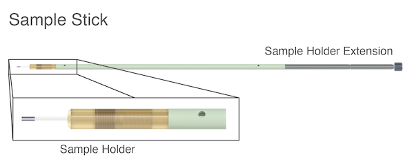
Sample Stick Assembly
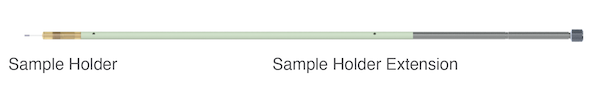
The Sample Stick Assembly consists of two parts (see figure above):
The Sample Holder (bottom part of the Sample Stick)
The Sample Holder Extension (top part of the Sample Stick)
In general, the sample capillary (or sample tube) is held (mounted) by the Sample Holder, which is then screwed on to the end of the Sample Holder Extension. The Cap at the end of the Sample Holder Extension can be easily removed to purge the Sample Stick with the cooling gas (e.g. helium or nitrogen) when inserting the Sample Stick into the probe. An o-ring will seal the Sample Stick. The entire Sample Stick is hollow to accommodate an optical fiber or electrical wires if desired.
The Sample Stick can be used for variety of sample tubes with different outer diameters up to 4 mm. For larger sample sizes up to 5 mm or smaller capillaries a custom modified sampler holder is required. Please contact Bridge12 at info@bridge12.com if you would like to request a customized Sample Holder.
For cold or cryogenic storage, the Sampler Holder with the sample capillary can be unscrewed from the Sampler Holder Extension to be stored separately.
3.2 - Sample Stick
The Bridge12 sample stick assembly
Sample Stick Assembly
The complete sample stick assembly is shown in the figure about. The sample tube is mounted in the Sample Holder. The entire assembly is designed to easily insert the sample into the probe at any operating temperatures.
Sample Holder
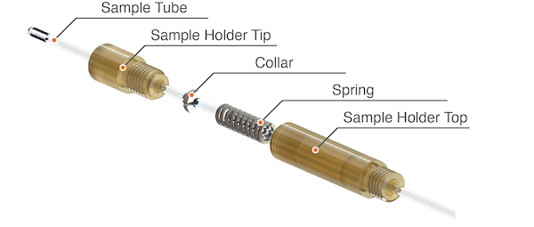
Sample Holder Parts
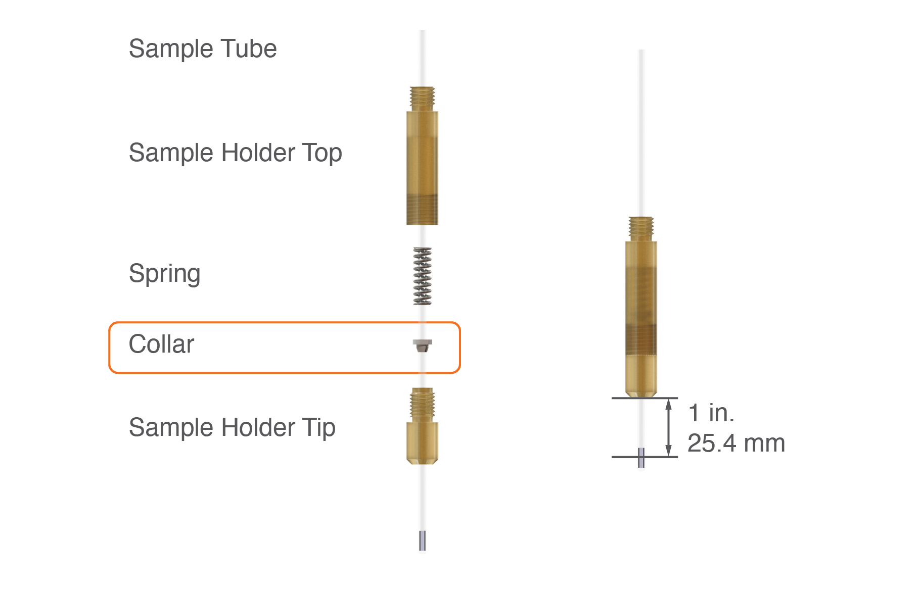
In addition to the sample tube the Sample Holder assembly consists of four different parts:
To accomodate different samples tube diameters, the Sample Holder comes with a set of different Sample Holder Tips and Sample Holder Tops.
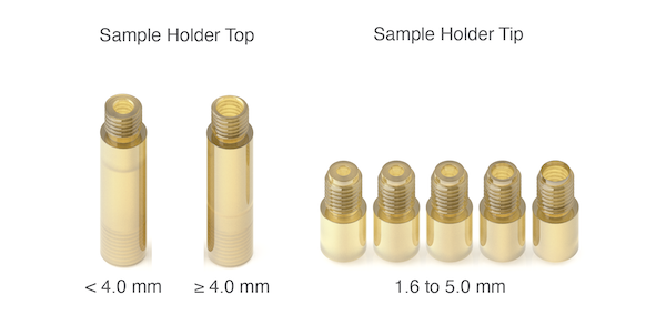
Sample Holder Parts
Two different sizes for the Sample Holder Top are included. Use the smaller Sample Holder Top (left side, figure above) size for sample tube with an OD of < 4.0 mm. For sample tube sizes of 4.0 mm and larger use the Sample Holder Top with the larger bore size (right side, figure above).
The Sample Holder Tip comes in sizes between 1.6 mm and 5 mm. Use the correct tip size according to the sample tube diameter.
Recommendation
Each sample tube and Sample Holder Tip show variations of the ID and OD. We recommend, test-fitting the capillary to the Sample Holder Tip before loading the sample into the capillary.
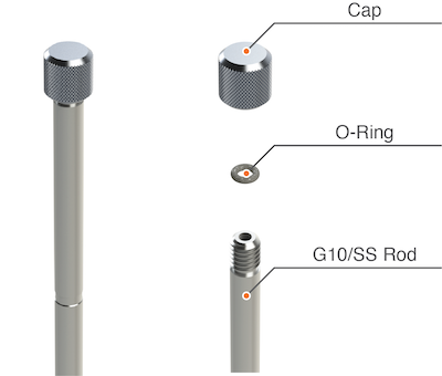
Sample Holder Extension
Sample Holder Parts
The Sample Holder Extension (shown above) consists of 3 different parts:
The Cap of the sample stick can be unscrewed to vent the insight of the Sample Holder Extension when operating the probe at low temperatures. An o-ring is used to seal the top of the extension.
By default and if not otherwise specified at the time of ordering the probe, the probe will be delivered with a closed Cap. However, to feed electrical wires or an optical fiber to the sample, the Cap can be replaced with one that has a center hole. For more information contact Bridge12 at info@bridge12.com
3.3 - Inserting and Changing a Sample
How to insert and change a sample
Preparing the Sample
Depending on the nature of your sample, either fill the sample tube with a powder, or pipette a liquid sample into the sample tube. In either case, check out the resonator specific recommended sample height.
For liquid samples, make sure all liquid made it to the bottom of the sample tube. Avoid any air bubbles when filling the sample into the sample tube. For powdered samples, tap the bottom of the sample tube several times to make sure all powder is at the bottom of the probe.
Warning
Use adequate safety precautions when handling your sample, especially when handling toxic materials.
Assembling the Sample Holder
To get started, the sample tube needs to be mounted in the Sample Holder.
Sample Stick Assembly
To mount the sample tube into the Sample Holder, follow these steps:
Select the correct Collar size, Sample Holder Tip and Sample Holder Top size according to the sample tube OD
Start with sliding the correct size teflon Collar over the sample tube. Make sure the Collar and the sample tube are oriented as shown in the figure above. The sample tube should slide in from the top to avoid damaging the Collar
Insert the sample tube with the Collar into the Sample Holder Tip
Slide the Spring over the sample tube. The orientation of the spring is not critical
Slide the Sample Holder Top over the sample tube. The entire assembly should like the one shown in the figure above
Begin screwing the Sample Holder Tip into the Sample Holder Top
As you screw in the Sample Holder Tip into the Sample Holder Top, the spring will compress the teflon collet. Depending on the number of turns the spring is compressed more or less. Try not to overtighten the assembly. You should still be able to slide the sample tube through the Sample Holder assembly.
Warning
Do not overtighten the Sample Haolder Tip. The Sample Holder should have a firm grip on the sample tube. Overtightening the Sample Holder Tip could break the sample tube.
Recommended Sample Height
By adjusting how much the capillary is sticking out of the Sample Holder Tip the user can control how far the sample is inserted into the resonator. In general, Bridge12 requires that the distance between the center of the sample and the bottom of the Sample Holder Tip is about 1 inch (25.4 mm).
This is shown in the figure above (right side).
Removing the Sample from the Sample Holder
To remove a sample tube/capillary from the sample holder, slightly loosen the end cap and pull the capillary out from the bottom of the sample holder.
In general, it is not necessary to disassemble the Sample Holder unless a sample tube gets stuck or breaks and the Sample Holder needs to be cleaned
Inserting the Sample into the Probe
Once the sample tube is securely mounted on the sample stick, it can be inserted into the probe through the sample holder turret. The sample holder turret assembly includes a knurled nut, washer (ferrule) and an O-ring as shown in the figure below.
To insert the sample follow these steps:
Stop the sample cooling (if running) and wait for the pressure in the cryostat to reach atmospheric pressure
Loose the knurled knut of the turret (It is not required to completely unscrew the knurled nut)
Remove the existing Sample Stick (or blind plug if present).
Make sure to insert the Sample Stick all the way to the bottom of the resonator. The Sample Stick should rest on the bottom of the Sample Holder Tip. The Sample Stick has a mark at the top. This mark should line up approximately with the top of the knurled nut
Under some circumstances, it may be easier to first assemble the sample stick with the knurled nut, the ferrule and the O-ring separately outside the resonator and load this assembly into the resonator. For this, additional spare parts are provided with the probe.
To remove the sample, reverse the above steps.
Warning
Do not force the sample stick into the probe (especially when operating at cryogenic temperatures). Forcing the sample stick into the resonator can potentially break the sample tube/capillary and case permanent damage to the probe.
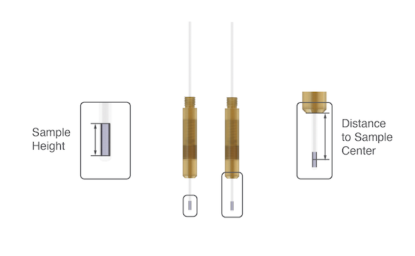
3.4 - Recommended Sample Amount and Position
Recommended sample amount and position for optimum performance
Important
Please check the recommended sample amount/height and position for the resonator you are planning to use. Each resonator will have its own optimum sample height. If you don’t find your particular resonator model in the list below, please contact Bridge12 at info@bridge12.com
When preparing a sample and mounting it in the Sampler Holder to factors are important to consider:
Sample Height: The sample height depends on the active volume of the resonator and is specific to the resonator model.
Distance to Sample Center: For the majority of Bridge12 resonators, the distance to sample center is 1 in. (25.4 mm). The distance may differ for some older resonator models. If you are not sure about the distance please contact Bridge12 at info@bridge12.com
Sample Amounts and Position
Resonator Model
Sample Tube OD
Recommended Sample Height (mm)
Distance to Sample Center
QLP
1.6 mm
> 5 mm (4.8 μl sample volume)
25.4 mm(1)
Footnotes
(1) Early prototype versions of the QLP resonator use 12 mm as the distance to sample center.
3.5 - Consumables
Consumables for Bridge12 EPR probes
Sample Tubes
For EPR spectroscopy we recommend using sample tubes manufactured by SP Wilmad-LabGlass. The following tube sizes can be used with the sample holder:
Other sample tubes can be used too, as long as they fit into the sample holder.
Warning
Only use sample tube/capillary sizes that are recommended by Bridge12 Technologies for the particular probe. Using sample tube/capillary that are too big for the probe can result in irreparable damage to the probe, the sample or both.
If you require additional sample holders, or sample holder extensions, please contact Bridge12 at ino@bridge12.com.
4 - Built-In Temperature Sensor
Most Bridge12 EPR probes have an integrated, calibrated Cernox temperature sensor. This allows the user to get an accurate reading of the sample temperature even when using a liquid cryogen-free (dry) cryostat with an exchange gas. The temperature sensor is compatible with all temperature controllers commonly used to regulate the cryostat temperature.
Temperature Sensor Calibration File
A calibration file for the temperature controller is available for download from LakeShore. If you can’t find the serial number for the temperature sensor please contact Bridge12 at info@bridge12.com with the probe serial number.
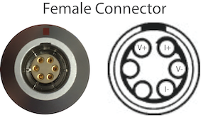
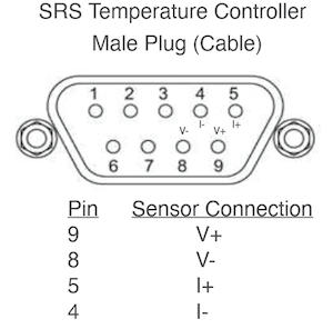
Electrical Connector
Bridge12 QLP Pinout
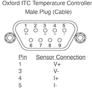
A 6-pin electrical connector is located on the top of the probe to connect the internal temperature sensor of the probe to a temperature controller. Two more pins are available to the user for auxillary connections. Upon request a connector with more pins (up to 9) can be installed. For reference, these are the connectors for the default configuration:
The Bridge12 QLP probe is equipped with an an integrated Cernox Temperature Sensor to measure the temperature close to the sample/resonator. This is especially helpful when using a liquid cryogen-free (dry) cryostat that uses an exchange gas. The temperature senor is located close to the actual sample position for an accurate reading.
Typically, the QLP probe will be shipped with a cable to connect the probe to a temperature controller. Please make sure you inform Bridge12 about the temperature controller you intend to use. For reference the pinout for two of the most commonly used temperature controllers is given in the next section.
For the most accurate temperature measurements a custom calibration table has to be used with the SRS CTC100 temperature controller. This file is typically provided with the probe. If you don’t have the calibration file please contact us as support@bridge12.com and provide the serial number of the probe and the model and make of the temperature controller you are using.
To use a custom calibration table you will need a USB stick (note, the file size of the calibration file is only a few kB).
To use the custom calibration table follow these steps:
Create a directory named cal within the top-level directory of a USB storage device.
Rename the CTC100 calibration file (this is a .txt file). The name of the file should be the name of the channel, with any spaces removed, plus .txt extension. If you don’t have a .txt file with the sensor calibration data contact us at support@bridge12.com.
Copy the file into the cal directory.
The calibration files are automatically loaded when the storage device is plugged into the instrument.
Some liquid cryogen-free cryostats require a mounting bracket to securely hold the probe in place and to dampen vibrations caused by the cold head. A support bracket is available for all Bridge12 EPR probes. Please reach out to support@bridge12.com if you require a support bracket.
The support bracket is mounted on the probe and securely locates the probe between the magnet coils.
Required Tools: The installation of the support bracket does not require any special tools. To secure the lock nuts, a wrench/spanner (size 7/16 or 12 mm) can be used.
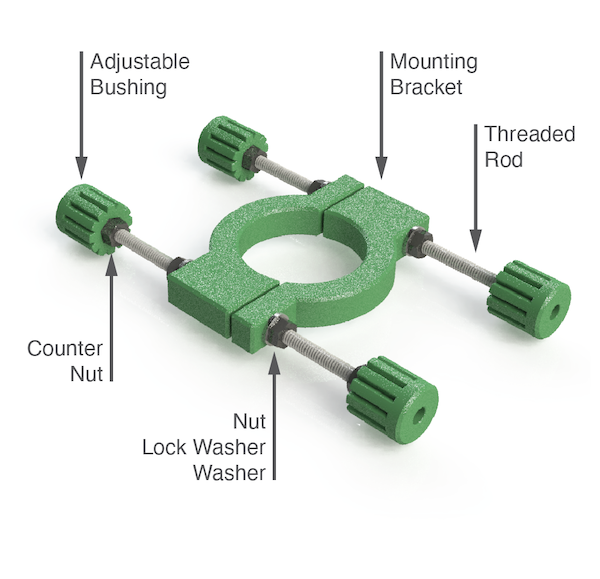
Parts of the Support Bracket Assembly
The mounting bracket assembly consists of the following components (refer to the figure):
To install the support bracket follow these instructions:
Place the mounting brackets around the flange adapter of the probe (stainless steel section of the probe top).
Insert both threaded rods.
First add 4 washers to the threaded rods, followed by 4 lock washers. Make sure the probe with the mounting brackets is roughly centered.
Add 4 nuts to each end of the threaded rod. These nuts are used to compress the mounting brackets around the flange adapter of the probe top. Screw the nuts all the way to the clamp. However, don’t tighten the nuts before the final position of the probe is set correctly.
Add 4 counter nuts to the threaded rod and screw them in so they are approximately half way between the nuts that compress the mounting brackets and the end of the rod.
Screw the adjustable bushings onto the threaded rod. The side with the nut should face the mounting bracket. Screw the bushing in until the threaded rod is almost sticking out on the opposite side. Repeat this for all 4 bushings.
Note
The adjustable bushings have a nut that screws onto the threaded rod. Sometimes, this nut can fall out ouf the bushing. Please make sure that there is a nut inside the bushing otherwise the bracket can not be secured between the magnet coils.
With the mounting bracket installed on the probe, insert the probe into the cryostat. The probe should be roughly at the correct height. If you are using the optical window, make sure the optical window of the cryostat and optical access of the probe are roughly aligned.
Make sure the probe is centered and the distance between the adjustable bushings and the outside of the magnet coils is roughly the same on both side.
Use the wrench to tighten the nuts to secure the mounting bracket around the probe top. Avoid overly tightening the nuts as this could damage the mounting brackets. The lock washers do not have to be completely compressed, but the mounting bracket should stay securely on the probe top.
Screw out the adjustable bushings until they almost touch the side of the magnet coil. Repeat this for all four bushings. You should still be able to move the probe up and down between the magnet coils.
Pull up the probe to the correct height and turn the adjustable bushings to securely lock the probe between the magnet coils. This is most easily done by two people. One person to hold the probe in place, while the other person adjusts the bushings to lock the probe in place. To avoid damages to the magnet coil, don’t overtighten the bushings.
Once the probe support bracket is in place, screw the
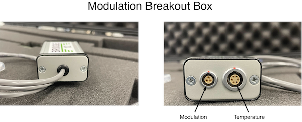
6 - Modulation Breakout Box
If your EPR probe has an integrated modulation coil for cw EPR spectroscopy the probe also comes with a breakout box to connect the modulation coil to the spectrometer (see figure below).
Modulation breakout box for EPR probes
The modulation breakout box is connected to the 6-pin connector of the EPR probe. The cable connecting the probe and the temperature controller is then connected to the breakout box. The modulation coil output of the spectrometer (or lock-in amplifier) is connected to the 3-pin connector of the breakout box.
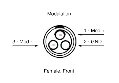
Modulation Coil Pinout
Modulation coil pinout
The modulation coil connector is a female LEMO connector. The figure above shows the front view of the connector. The same direction a user would look at the connector when holding the breakout box in their hands. The pinout numbering follows the default numbering scheme for this type of connector:
1 - Mod - : Modulation coil.
2 - GND : Probe ground.
3 - Mod + : Modulation coil.
Note: The modulation coil is not internally grounded (floating).
Please contact Bridge12 at support@bridge12.com if you have further questions how to connect the modulation output of your spectrometer or lock-in amplifier to the modulation breakout box.
The pinout for the temperature connector can be found here.