This is the multi-page printable view of this section. Click here to print.
System Installation
1 - Installing Open VnmrJ (Bridge12 Version)
The following pages provide a step-by-step guide how to install the Bridge12 version of OVJ and getting the computer ready for your first NMR experiment.
System Requirements
The following computer hardware will be required:
| Parameter | Requirement |
|---|---|
| Computer | 64-bit System |
| Free Disk Space | > 4 GB |
| Operating System | Ubuntu 20.04 LTS system |
| Python | Python (> 3.8) pyserial (version 3.5) |
This installation guide assumes that you are installing OVJ_B12 on a clean installation of Ubuntu 20.04 LTS. To install OVJ, please create an user account called vnmr1 during the installation process. This should be an account with administrator rights.
Once the Ubuntu installation is finished, please log in as this user.
1.1 - Installing OVJ-B12
Note
Open VnmrJ is automatically installed when installing OVJ-B12, the Bridge12 version of OVJ. OVJ does not have to be installed separately.
Bridge12 does not offer a pre-compiled version of OVJ-B12. Instead, the package has to be build on the computer that is used to operate the spectrometer. However, the installation process is streamlined and does not require any specific programming skills besides navigating through some terminal windows.
Preparing the System
-
Start by opening a terminal window and update all installed packages to the latest version:
1
2
sudo apt-get update sudo apt upgradeThe best way to install OVJ-B12 is by using the GitHub repository. Updates are pushed to the GitHub repository and can be installed by the user from there.
-
Install git and python3-pip
1
2
sudo apt install python3-pip sudo apt install gitTo communicate with the NMR spectrometer and the Bridge12 MPS a serial connection to the periphery is required. OVJ-B12 uses Python and the pyserial Python package for this purpose, which can be installed through pip.
1sudo pip3 install pyserial==3.5
Cloning the Repository
-
To clone the GitHub repository, open a terminal window
1git clone git@github.com:Bridge12Technologies/OpenVnmrJ_B12TOnce the repository is downloaded change into the directory …..
Building the OVJ-B12 Package
-
Build the package. As a first step in the installation, the OpenVnmrJ and ovjTools repositories will be automatically downloaded. The complete build processes takes about 10 minutes.
1sudo ./buildb12We recommend opening a new console tab in the terminal window to monitor the build process. To do this copy and paste the command (tail -f) with the corresponding file shown in the console after starting the build process into the new console tab of the terminal window.

-
Once the build is finished check the build process with
1./whatsinThe output should report 0 Errors and 0 Build Terminations for a successful build.
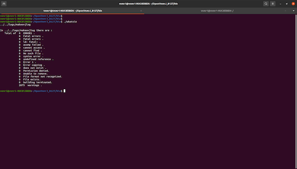
If the build succeeded the folder ~/ovjbuild/dvdimageB12 is created.
Install OVJ-B12
-
To install OVJ-B12 change to the dvdimageB12 directory and execute ./load.nmr
1
2
cd ~/ovjbuild/dvdimageB12 ./load.nmrA popup window will appear, press install to continue with the installation.

-
When asked to update users start the vnmrjAdmin program located on the Desktop. The program should start automatically. In vnmrjAdmin go to Configure -> Users -> Update users …
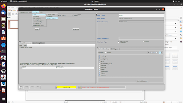
and add all users (vnmr1, service and walkup if they were created) to the right side. Then press “update users”

Once all users are updated, the bottom status line in OpenVnmrJAdmin will show “Update User Completed All Requested Users”. Once you see this message, close OpenVnmrJAdmin.
-
After this, the system will open a new terminal window and the user has to answer a few questions. Please answer both questions with y(yes).
1
2
Standard configurations include the walkup and service accounts. Would you like to make them now? (y/n)1 2Shall this system be configured as a spectrometer (see image below). Would you like to configure it now? (y/n)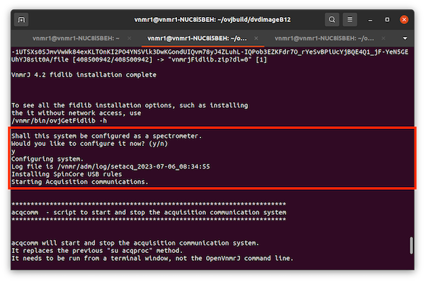
-
Installing NMRPipe is optional and can be answered with n(no).
-
We recommend to install the OVJ manuals. When asked to install the manuals please answer the question with y(yes).

Finish Installation
-
Once the load.nmr script has finished the upgrade.nmr script should be executed
1./upgrade.nmr -
The installation scripts places two icons to the Desktop: vnmrj and vnmrjAdmin. vnmrj can either be launched by double-clicking on the desktop icon or from the command line:
1vnmrjIt is convenient to add Open VnmrJ to the quicklaunch menu. This can be done by by searching for “openvnmr” and then dragging the program icon to the quicklaunch bar.
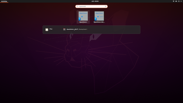
OVJ-B12 is now installed and ready for its first experiment.
2 - Setting Up the Hardware
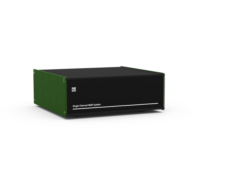
System Description
Front Panel Connectors
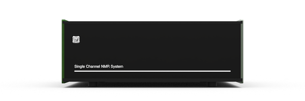
Bridge12 SCN Front Panel Connectors
The NMR probe is connected to the Bridge12 SCN using the SMA connector located on the front panel of the system.
Back Panel Connectors
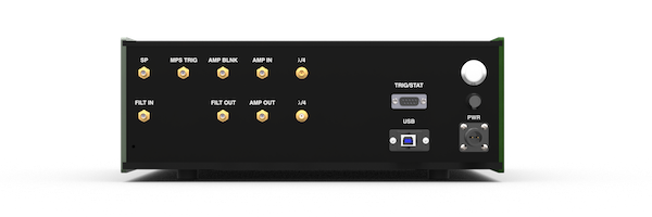
Bridge12 SCN Back Panel Connectors
Most connections for the Bridge12 SCN are located on the back panel.
| Connector Label | Style | Description |
|---|---|---|
| USB | USB-B | USB connection to spectrometer computer |
| PWR | Circular | System power connection. The input voltage for the system is 24 VDC, 1.25 A. To power the system, please use the power (desktop) adapter that was delivered with the system. |
| FILT IN FILT OUT |
SMA(f) | Receiver input filter (bandpass). The bandpass filter is used to reduce the noise in the system. By default the Bridge12 SCN comes with a bandpass filter for 1H NMR spectroscopy. If you like to operate the system at a different Larmor frequency the filter has to be replaced with a bandpass filter for the desired frequency. Additional filters can be found on the MiniCircuits webpage. |
| λ/4 | SMA(f) | Connection for the λ/4 cable. The Bridge12 SCN uses a passive Transmit/Receive (T/R) switch to protect the receiver. For this an appropriate λ/4 needs to be conneted to the two connectors. By default the system comes with a λ/4 cable for 1H NMR spectroscopy. If you wish to study other nuclei you need to replace the 1H with a cable with a different length. Instructions to make your own cable can be found on the webpage for the OpenTRSwitch or contact Bridge12 at support@bridge12.com. |
| AMP IN | SMA(f) | External amplifier input. |
| AMP OUT | SMA(f) | External amplifier output. |
| AMP BLNK | SMA(f) | Blanking gate for external amplifier. The blanking gate is active low. If you have questions about how to connect an external amplifier please contact Bridge12 at support@bridge12.com |
| MPS TRIG | SMA(f) | Trigger pulse for the Bridge12 MPS to modulate the output power. The trigger is active high. |
| SP | SMA(f) | Not used. |
| TRIG/STAT | D-Sub (f) | Auxiliary connector. Pinout: 1: 10 MHz reference for external use, 2, 3: Not connected, 4: Hardware trigger, 5: Hardware reset, 6, 7, 8, 9: GND |
Fuse
A fuse holder is located on the back panel of the SCN. If necessary, the user can replace the fuse. The dimensions are 5x20mm and the fuse should have a rating of 1.25A.
Placing the System
- Place the Bridge12 SCN close to the EPR spectrometer. It is recommended to keep the length of the cable connecting the probe to the system at a minimum length.
- The system should rest on a stable surface.
TRIG/STAT Channel Explanations
- 1 - 10 MHz Reference:
- The 10 MHz reference is the master oscillator output
- 4 - Hardware Trigger:
- When this is pulled to GND an acquisition resumes or starts
- 5 - Hardware Reset:
- When this is pulled to GND the pulse program is reset - as long as this is low no pulses are generated and sent out
- 6/7/8/9 - Ground
Connecting the System
Electrical Connections
To power the SCN connect the external power supply to the PWR connection. then connect the USB-C port to a PC. Connect the input of a bandpass filter corresponding to your NMR frequency to the ‘FILT OUT’ connector and the output of the bandpass filter to the ‘FILT IN’ connector. Connect a \(\lambda\)/4 filter (e.g. a cable with the correct length) for your NMR frequency to the \(\lambda\)/4 connectors.
Connecting the NMR Probe Circuit
Changing the RF Filters
Not sure if we need this right now.
2.1 - Connecting the NMR Probe
The connector to connect the NMR probe to the Bridge12 SCN spectrometer is located on the front panel. The input impedance is 50 Ω.
If your probe has a BNC connector please use a SMA-BNC Adpater and a BNC cable to connect the probe.
2.2 - Connecting an External Amplifier
The Bridge12 SCN has an internal RF power delivering up to 2 W output power. For many (low frequency) experiments this power is sufficient.
If the available power from the internal amplifier is not sufficient, an external high-power RF amplifier can be connected to the system.
To connect an external amplifier the input of the external device must be connected to the AMP OUT connection on the back panel of the SCN. The output of the external amplifier must be connected to the AMP IN connection located on the back panel.
To blank the external amplifier, connect the blanking gate to the AMP BLNK output of the SCN. The blanking gate is active low.
Specifying the Amplifier pre-Blanking Time rof1
To use an external amplifier with blanking, the amplifier needs to be unblanked before sending the RF pulse. Amplifiers typically require a short time unblank. This time can be specified using the OVJ parameter rof1. The value is typically given by the manufacturer in the data sheet of the amplifier.
The value can be set from the OVJ command line:
|
|
If the required value is larger than the default value, for rof1 can be changed using the setlimit command as shown below.
|
|
Enabling the External Amplifier and Setting the Drive Level
OVJ needs to be connected to use the external amplifier. This is done from the OVJ command line:
|
|
The B12SCNControl('state?) command can be used to query the state of the amplifier. If the system returns “extamp” the external amplifier is enabled.
|
|
The drive level (input power) of the external amplifier can be set using the OVJ command line by specifying the value stored by tpwrf.
|
|
To disable the internal amplifier from the OVJ command line enter this command:
|
|
If the command B12SCNControl('state?) returns “intamp”, the internal amplifier is used. The tpwrf value is automatically set to 100 (the maximum).
Warning
The drive level for the external amplifier is by default set to 3 dBm (2 mW - corresponding to tpwrf=3.25). This value can be changed using the tpwrf command from the OVJ command line. Please consult the data sheet of the external amplifier to find out the correct drive level for you amplifier model. The value in tpwrf is a linear scaling factor.
2.3 - External Trigger
The acquisition of an NMR spectrum by the Bridge12 SCN system can be triggered using an external trigger. The external trigger is connected to the TRIG/STAT connector located on the back panel. The pinout for the connector is given in the section describing the Back Panel Connectors.
The trigger is active low on the falling edge. This means, pulling pin 7 on the TRIG/STAT connector to GND will start the acquisition of an NMR spectrum. By default every acquisition needs to be triggered. If you require a different behavior (e.g. trigger 4 acquisitions to complete a phase cycle) the pulse program need to be changed accordingly. For further information please contact Bridge12 at support@bridge12.com.
The system also has a hardware reset, accessible through pin 9 on the TRIG/STAT back panel connector. When this pin is pulled to GND, the pulse program will reset. As long as the hardware reset of the SCN (pin 9) is pulled to GND no RF pulses are generated and send to the amplifier. Acquisition of an NMR spectrum is not possible.
Enabling the External Trigger
The external trigger needs to be enabled in OVJ for the user to be used. This is done either:
-
from the OVJ command line:
1B12HWTriggerFlag=1 -
by setting the value in the Enable HW Trigger (in the Acquisition tab) to 1

- or by activating the HW Trigger checkbox in the 1H tab

Disabling the External Trigger
To disable the external trigger use the command
|
|
or set the value in the Enable HW Trigger box to 0 (Acquisition tab) or disable the checkbox in the Default 1H tab.