Many Bridge12 (high-field) EPR spectrometers use superconducting magnets manufactured by CRYOGENIC LTD. The magnet system comes with extensive documentation.
All information provided here is specific to superconducting magnets specifically manufactured to be used in Bridge12 instruments. In addition, most instructions here describe procedures for day-to-day operations.
1 - Magnet Installation
Supporting Information for Magnet Installation
During the initial installation of the spectrometer, the magnet will be installed by an engineer from Cryogenic Ltd. Once the magnet is installed and passes the customer acceptance test no further installation steps are necessary.
If you have any more questions please reach out to:
Please make sure to read the instructions for cooling down the magnet carefully. Make sure you don’t have any questions and all required equipment is in place.
These instructions are not to be used for initial cooling down of the magnet. For these instructions it is assumed that the magnet was properly decommissioned by Bridge12 or CRYOGENIC.
If you have additional questions please do not hesitate to reach out to Bridge12 or CRYOGENIC.
Required Equipment
For cooling down the magnet or recharging the helium reservoir of the integrated VTI (iVTI) the following additional equipment is required:
Vacuum pump, preferable a turbomolecular pump with a capacity of 12 m3/hr.
Various vacuum hoses, matching center rings and clamps
High grade helium gas (grade 5). This is only required for recharging the helium compressor or the helium reservoir of the iVTI. For changing the sample regular grade helium gas is sufficient.
Hoses, fittings, pressure regulator, etc. to connect the helium cylinder to the iVTI.
1. Evacuation of the Magnet Cryostat
The magnet cryostat has a single vacuum space which is evacuated via the bellows sealed valve fitted to the cryostat top plate. As a guide, this space should be evacuated using a pump with a capacity of at least 12 m3/hr and a base pressure of <10-4 mbar. Outgassing of the superinsulation occurs whenever the cryostat is allowed to warm up to room temperature. Also, after a magnet quench it is sometimes necessary to evacuate the magnet cryostat, especially if you can’t reach the normal base temperature of the magnet after a quench.
To evacuate the magnet cryostat, connect a vacuum pump to the vale located at the top of the cryostat. Start the vacuum pump and once the pump has reached its base pressure open the valve to the magnet cryostat. The cryostat should be pumped down to a pressure of <10-3 mbar before attempting to cool down. If the pressure decrease is slow, this may be an indication of moisture in the superinsulation which will require more extended pumping of the interspace.
Under normal circumstances there is no need to vent the vacuum space to atmospheric pressure. It is strongly recommended to not vent the vacuum space to decrease the time it takes for the magnet to come up to room temperature. If you have to vent the magnet cryostat please consult the instructions in the magnet manual or contact CRYOGENIC.
2. Prior Checks Before Cooling Down the Magnet
Before cooling down the magnet, please observe the following operational checks:
Magnet
The cryostat vacuum space is adequately evacuated to a base pressure of <10e-3 mbar
The compressor is connected to the electrical mains according to the supply information on the compressor housing. Please refer to the compressor manual for further information regarding power requirements.
Adequate water cooling is provided for the compressor (water-cooled versions only). Please refer to the compressor manual for the correct specification for the water circuit.
Both ends of the flexible hoses connecting the compressor to the cold head are properly tightened. Make sure the charcoal trap is installed. Please use the supplied tools to tighten all connections.
The electrical lead from the compressor to the cold head is connected.
The current leads running from the magnet power supply are securely attached to the magnet terminals.
The magnet coil is electrically isolated from the cryostat. To check this, measure the resistance between a magnet current terminal and one of the cryostat top plate outer fixing bolts. A value of ≥ 500 kΩ is typical.
The temperature monitors/controllers are installed properly and the lead(s) are connected.
The static helium pressure in the compressor is correct to ensure it is at the recommended value. Please refer to the compressor manual for the correct specification of the helium pressure. If the pressure is lower than expected please follow the instructions in the compressor manual before starting the compressor.
The system is properly positioned such that there are no significant ferromagnetic objects (e.g.; steel beams, pumping stations etc) close to the cryostat. It should be noted that structural supports on the floor must also be considered when positioning the cryostat. Please contact CRYOGENIC if you are unsure about the possible influence of magnetic objects adjacent to the system.
integrated VTI (iVTI)
The dry pump for the iVTI is connected to an outlet. At this time, the dry pump is not powered on.
The external gas reservoir must be charged to the correct pressure with clean helium gas and connected to the cryostat (see system specification). The reservoir is connected to the iVTI gas circuit via a face-sealing connector.
It is recommended that the flow through the iVTI is checked at room temperature prior to cooling down the magnet.
Make sure the dry pump bypass valve (V16) is closed and th helium reservoir valve (V12) is opened.
Make sure the iVTI butterfly valve is open
Switch on the dry pump and pumping for a short time on the iVTI head with the needle valve fully open and circulating gas through the external dump as in normal operation at cold temperatures. The expected flow should be in the range of 5-15 mbar.
Having checked the room temperature flow, switch oof the dry pump
Open the bypass valve (V16). This allows gas to circulate via natural convection throughout the gas circuit during the cooldown of the magnet. The convective flow helps to cool the internal components of the gas circuit whilst minimizing the wear of the pump.
Charge the static column, the space where the resonator is located, to 1 atmosphere of clean helium gas from an external source of helium. The gas is necessary to conduct heat from the wall of the static column and maintain a small temperature differential between the helium flowing in the annular space around static column and the sample probe. It is recommended to charge the static column prior to cooldown as once the system is cold it is more difficult to judge the quantity of helium being added due to condensation of the gas as it enters the column. The approximate volume of the static column is .05 litres.
Cooling Down the Magnet
Once all prior checks have been completed (see instructions above) the magnet cooldown can be started. It is recommended, that the system monitor is started to log all temperatures during the cooldown process.
Cooling the magnet is simply a matter of starting the helium compressor:
Turn the switch located on the back of the compressor into the ON position.
Press the ON button to start the compressor.
Typically the 1st stage of the cryocooler will cool fastest followed by the 2nd stage and then the magnet. For this magnet, the cooldown time is typically about 22 hrs. It should be noted that initially, the operating pressure at the compressor will be high and then reduce (typically by 20 %) as the magnet temperature drops and the cryocooler is required to do less work to remove heat from the system. Once the base temperature of the magnet is achieved the magnet may be energized.
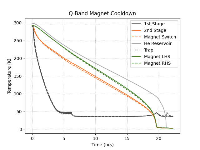
Temperatures of a Typical Magnet Cooldown
Temperatures for a typical cooldown of the magnet are shown in the figure above. The following table has shows some typical temperatures once the magnet is at its base temperature.
Q-Band Magnet with iVTI Base Temperatures
Parameter
Value
Parameter
Value
Cryocooler 1st stage
36.2 K
Persistence Switch
3.0
Cryocooler 2nd stage
3.0 K
Helium pot (Not heated)
3.0 K
Magnet LHS winding
3.0 K
Helium pot (heated)
3.2 K
Magnet RHS winding
3.0 K
Charcoal trap (not circulating)
46.6 K
Checking the iVTI Operation
Once the magnet has avhieved base temperature:
Close the bypass valve (V16) across the dry pump.
Make sure the cryostat heater is switched off.
Start the dry pump.
Adjust the needle valve to a pressure of approximately 6 mbar at the iVTI pump port. Please note the needle valve may require several further adjustments as the temperature profile within the flow circuit varies whilst steady-state flow conditions are established in the circuit.
For further information/instructions on how to operate the iVTI please see the section about operating the iVTI.
3 - Warming Up the Magnet
How to warm up the magnet
Warning
Please make sure to read the instructions for warming up the magnet carefully. Make sure you don’t have any questions and all required equipment is in place.
If you have additional questions please do not hesitate to reach out to Bridge12 or CRYOGENIC.
Once experiments are finished and the user anticipates some considerable downtown when no experiments are planned the magnet can be warmed up to room temperature. To warm up the magnet:
Make sure the field is at 0 T. This can be verified either in the spectrometer control software or on the front panel of the magnet power supply.
Make sure the spectrometer logger is running and is recording vital data of the system.
To switch off the helium compressor press the off switch located on the back of the device. Once the compressor is switched off, the magnet starts immediately to warm up. It is recommended that the system then be left to attain room temperature naturally which will take approximately 36 - 48 hours.
Warning
Do not disconnect the compressor hoses for any reason during the warm-up of the system. The gas in the cryocooler head must be allowed to expand into the reservoir volume located in the compressor.
It is common practice to break the interspace vacuum when required to warm a cryostat more rapidly than would otherwise occur naturally. CRYOGENIC strongly discourages users from venting the vacuum interspace for any reason.
The radiation shield may collapse if subject to an appreciable pressure differential (i.e. by opening the cryostat vacuum valve too quickly).
When the user is ready to continue experiments the magnet needs to be cooled down. Please follow the instructions in the Magnet Cooldown Section.