This is the multi-page printable view of this section. Click here to print.
Accessories
- 1: Active Electric Shims
- 1.1: Installation
- 1.2: Specifications
- 2: Microwave Power Source
- 3: Goniometer
1 - Active Electric Shims
Welcome to the online documentation of the Bridge12 Active Electric Shims (AES) for electromagnets.

Bridge12 Active Electric Shims (AES)
The Bridge12 AES can be installed in an electromagnet with horizontal field orientation, commonly used in EPR spectroscopy. In total 5 different coils are included to actively control the Z1, Z2, X, and Y gradients. In addition a B0 (Z0) coil is integrated to perform small field adjustments.
Please follow the installation and operation instructions. If you have further questions please contact Bridge12 at support@bridge12.com.
1.1 - Installation
Before You Start …
Important
You heard it many times. Before you start assembling the shims we suggest first reading the complete installation instructions to the end and make yourself familiar with the different components. To assemble the shims no further tools are required.
Warning
To install the shims, make sure the magnet is switched off.
What is Included
The Bridge12 AES come by default with the following parts (see figure below):
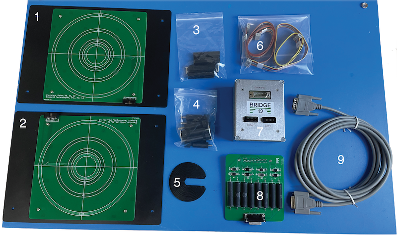
Bridge12 Active Electric Shims (AES) components
- Electrical Shims (right side, qty.: 1)
- Electrical Shims (left side, qty.: 1)
- Shim spacers (qty.: 4)
- Shim supports (qty.: 8)
- Adjustment/tightening tool (qty.: 1)
- Cables to connect shims to shim interface (qty.: 2)
- Shim interface (qty.: 1)
- Shim board adapter for Bruker BSMS shim power supply (qty.: 1)
- Cable to connect shim interface (7) to Bruker BSMS shim board adapter
Assembling the Shims
Important
Assembling the shims is best done by two people.
The electrical shims are supported between the magnet poles using a total of 8 shim supports and 4 shim spacers (shown in figure below).
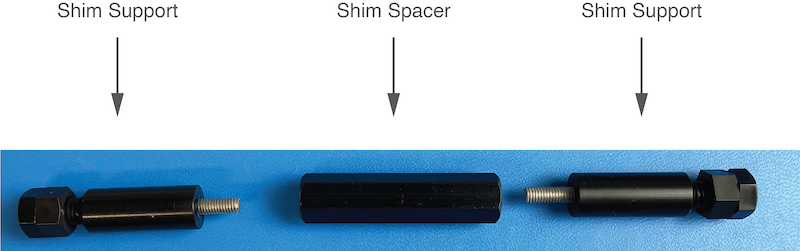
Shim Supports (left, right) and Spacer
To assemble the shims:
- Place the electrical shims (1 and 2) at the side of the magnet. The board labeled “left” should face the left magnet pole. The board labeled “right” should face the right magnet pole. The labels are located on the back of the boards.
- Place the shim spacer between the shim boards
- Screw in the shim supports on both side.
The assembly should look similar to the assembly shown in the figure below.
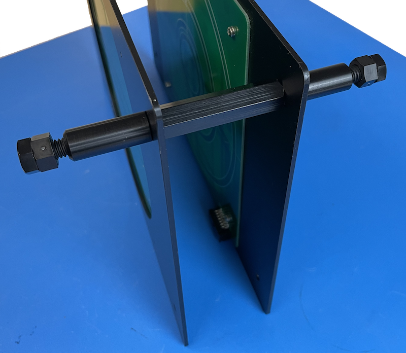
Shims with one set of supports and spacer assembled
- Repeat the previous step for all shim supports and spacers.
Alternatively, you can first assemble the shim boards using the supports and the spacers outside the magnet and place the assembled shims between the magnet poles.
Under some circumstances it is not possible to use all 8 shim supports. In this case two supports can be omitted and replaced by two screws as shown in the following image. However, make sure when locking the shims in place that their position is fully secured and that the shims won’t slide down. We don’t recommend removing more than one set of shim supports.
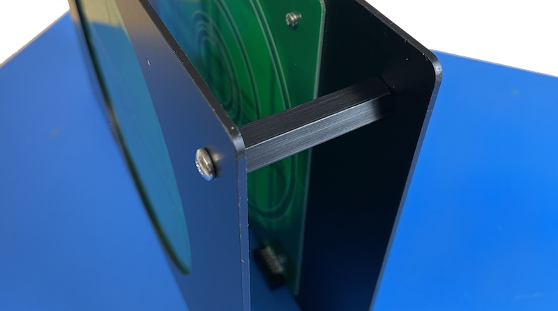
Shims with spacer only
Locking the Shims in Place
Once you have assembled the shims and placed between the magnet pole pieces, you need to lock the shims in place. Each support of the shims has an adjustment screw and a counter nut (see figure below). Before you start turn the counter nut to face the screw as shown in the figure below.
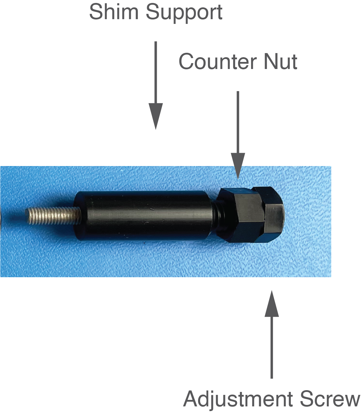
Shim Supports with adjustment screw and counter nut
To hold the shims between the magnet poles, turn the adjustment screws on all sides, until they touch the side of the magnet. Make sure the shims are centered between the pole pieces of the magnet. To turn the screws, especially when the tops of the screws are close to the sides of the magnet use the Adjustment/Tightening tool.
Once the shims are supported between the magnet poles, lock the adjustment screws by turning the counter nut until it touches the shim support. Make sure the nut is not overtightened.
The picture below shows the shims installed in an electromagnet for EPR spectroscopy.
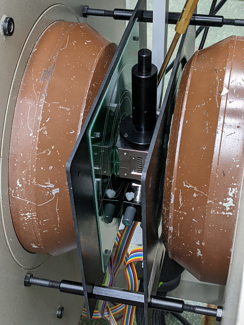
Picture of the installed shims (courtesy of Prof. Song-I Han, UCSB
Connecting the Shims
To use the shims, the following connections have to be made:
- Shims to shim interface
- Shim interface to shim power supply
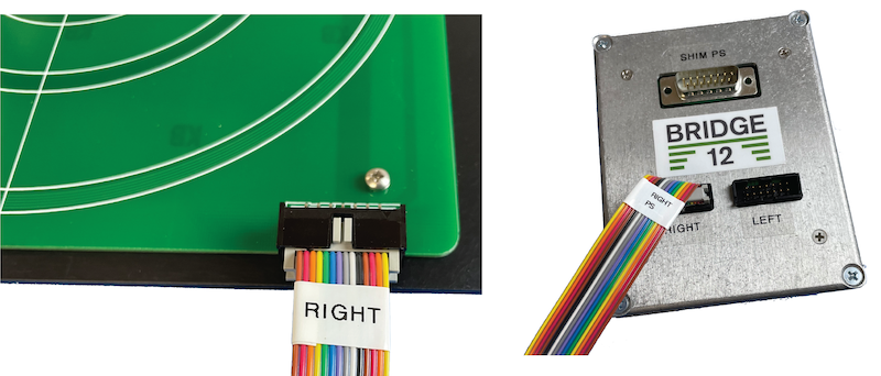
Connecting the shims to the shim interface
To connect the shims to the shim interface follow these steps:
- Starting with the shims located to the right, connect the ribbon cable marked “RIGHT” to the right shim board.
- Connect the same ribbon cable the shim interface.
- Repeat the step for the ribbon cable marked “LEFT”.
Connecting the Shims to a Lab Power Supply
The shims can be operated using any benchtop lab power supply. For convenience a multi-channel power supply can be used. Often these power supplies are not bi-polar, in which case you need to swap the leads of the respective channel if you would like to reverse the gradient (e.g. Z1 to -Z1). The power supply can be directly connected to the 15 pin sub-D connector of the shim interface.
| Pin# (sub-D) | Shim Connection | Pin# (sub-D) | Shim Connection |
|---|---|---|---|
| 1 | Z(B)0 (s) | 2 | Z(B)0 (r) |
| 3 | Z1 (s) | 4 | Z2 (r) |
| 5 | Z2 (s) | 6 | Z2 (r) |
| 7 | X (s) | 8 | X (r) |
| 9 | Y (s) | 10 | Y (r) |
| 15 | GND | Shield | GND |
| (GND - Ground, s - supply, r - return) |
Connecting the Shims to a Shim Power Supply
The shims can be operated using a shim power supply e.g. of a NMR spectrometer. The following instructions are specific to a shim power supply used in Bruker NMR consoles (courtesy to Prof. Song-I Han, UCSB).
To connect the shims to a Bruker shim power supply (e.g. BSMS/2) follow this steps:
- Connect the shim board adapter to the the shim power supply (see image below, left).
- Connect the 15 pin sub-D cable to the shim interface.
- Connect the 15 pin sub-D cable to the shim board adapter.
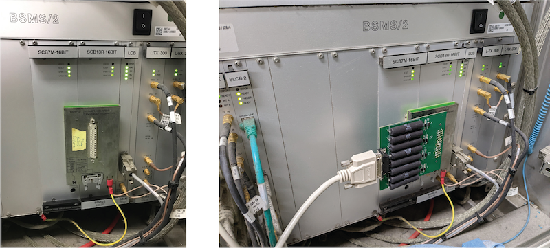
Connecting the shims to the Bruker BSMS/2 shim power supply (images courtesy Prof. Song-I Han, UCSB
Once you have made these connection, the shim can be controlled through the shim power supply.
If you need help at any step of the installation please contact Bridge12 at support@bridge12.com.
1.2 - Specifications
The Bridge12 Active Electric Shims (AES) are a 5 channel shim system for electromagnet with a horizontal field. These magnets are typically used in Electron Paramagnetic Resonance (EPR) spectroscopy. The five channels or the shims are: Z0 (or B0), Z1, Z2, X, and Y. Each channel can operate at a current of up to 1.5 A.
| Parameter | Value |
|---|---|
| Number of channels | 5 |
| Maximum current/channel | 1.5 A |
| Spacing | 53 mm |
Warning
Do not exceed a current of (+/-) 1.5 A per channel to avoid permanent damage to the shims.
Shim Interface Pinout
| Pin# (sub-D) | Shim Connection | Pin# (sub-D) | Shim Connection |
|---|---|---|---|
| 1 | Z(B)0 (s) | 2 | Z(B)0 (r) |
| 3 | Z1 (s) | 4 | Z2 (r) |
| 5 | Z2 (s) | 6 | Z2 (r) |
| 7 | X (s) | 8 | X (r) |
| 9 | Y (s) | 10 | Y (r) |
| 15 | GND | Shield | GND |
| (GND - Ground, s - supply, r - return) |
If you need help at any step of the installation please contact Bridge12 at support@bridge12.com.
2 - Microwave Power Source
We are currently updating the online documentation for the Bridge12 Microwave Power Source (MPS) for ODNP spectroscopy. In the meanwhile, please visit mps.bridge12.com for the previous version.
3 - Goniometer
The goniometer is an attachment for Bridge12 EPR probes, such as the Bridge12 XLP. The accessory is attached to the top of the probe and allows the user to rotate the sample stick around its axis. The goniometer accessory can be fully remote controlled from a terminal window. A Python package is available to allow for complete integration into the spectrometer software.
3.1 - Remote Control the Goniometer
Getting Started
Installing the pyB12SMC Python Package
Requirments
The pyB12SMC Python package requires:
The pyB12SMC Python package to remote control the goniometer is available on GitHub (pyB12SMC). To install the Python package follow these steps:
-
Clone the Python package from the GitHub repository.
-
Open a terminal window and navigate to the folder to which the Python package was downloaded. For example, if you cloned the repository to C:\Documents\Repositories\pyB12SMC navigate to the folder C:\Documents\Repositories
-
In the terminal window type the following command and hit the return key:
pip install -e pyB12SMC
Then the Python package will be built and installed locally. Once it is installed you can verify using the pip show command that the package is properly installed:
    B12TManuals % pip show pyB12SMC

    Name: pyB12SMC
    Version: 0.0.1
    Summary: A Python package for interfacing with Stepper Motor Controller (BIGTREETECH SKR MINI E3 V3.0) used in Bridge 12 Technologies products.
    Home-page: http://www.bridge12.com/
    Author: Bridge12 Technologies, Inc
    Author-email: yhuang@bridge12.com
    License:
    Location: /Library/Frameworks/Python.framework/Versions/3.12/lib/python3.12/site-packages
    Editable project location: .../Documents/Repositories/pyB12SMC
    Requires: numpy, pyserial
    Required-by:
The Python package is properly installed and the goniometer can be controlled using the methods in pyB12SMC.
Quickstart - Using the pyB12SMC Python Package
Important
The goniometer rotation is controlled using a stepper motor and the motor is connected to the X axis of the stepper motor controller. Therefore, all commands used to control the goniometer need to reference the X axis..
Once the package is installed open a terminal and start Python. To use the goniometer follow these steps:
-
Import the Python package
import pyB12SMC -
Initialize the class
smc = pyB12SMC.SMC() -
Try the following commands:
Go to the home position (X-axis), corresponding to 0º
smc.home('X')Set the position of the goniometer to 15º
smc.theta('X', 15)Nothing will happen if the command is repeated since the angle theta is an absolute value. To return to the home position either use one of these two commands:
smc.home('X')or
smc.theta('X', 0) -
To change the behavior from absolute angle to relative angle use the following command:
smc.relative(True)Now, each time the smc.theta command is issued the goniometer rotates by the given angle. For example:
smc.theta('X', 15)smc.theta('X', 15)Will result in a total rotation of 30º.
Sending the following command:
smc.theta('X', -15)will rotate the goniometer 15º in the opposite direction.
-
To print an overview of the available methods send the following command:
smc.help()
Troubleshooting
No Serial Communication
If the communication with the controller fails or the device cannot be found, it is possible that the Python package cannot find the device on the COM port. In this case, a COM port can be specified manually. To set the COM port manually (here COM13) send the following command:
smc = pyB12SMC.SMC('COM13')
Method Overview
When starting the Python package an object is created. The methods included in the class are described below.
Important
Valid values for the parameter axis are “X”, “Y”, or “Z” (capital letters)
| Method | Returns | Description |
|---|---|---|
| move(axis, position) | None | Move axis linearly. Position given in mm. |
| theta(axis, theta) | None | Move axis rotationally. The angle is given in degrees. |
| feedrate(axis, feedrate) | None or value (dictionary) | Query the information of federate if no arguments, or set axis feedrate in units/s |
| position(axis, position) | None or value (dictionary) | Query the information of positions if no arguments, or set axis position in unit |
| current(axis, current) | None or value (dictionary) | Query the current settings if no arguments, or set axis current in mA |
| steps_per_unit(axis, step) | None or value | Query the resolutions of all axis if no arguments, or set axis resolution in steps/unit |
| home(axis) | None | Home all axis if no argument, or home specified axis |
| set_home(axis) | None | Set current positions as home for all axis if no argument, or set current position as home for an axis |
| relative(enable) | None or boolean | Query the movement type if no arguments, set movement relative or absolute |
| save() | None | Save settings to EEPROM |
| restore() | None | Restore settings from EEPROM |
| reset() | None | Reset configuration to factory defaults |
| send_command(command, receive) | None or string | Send command to a device and receive information from a device |